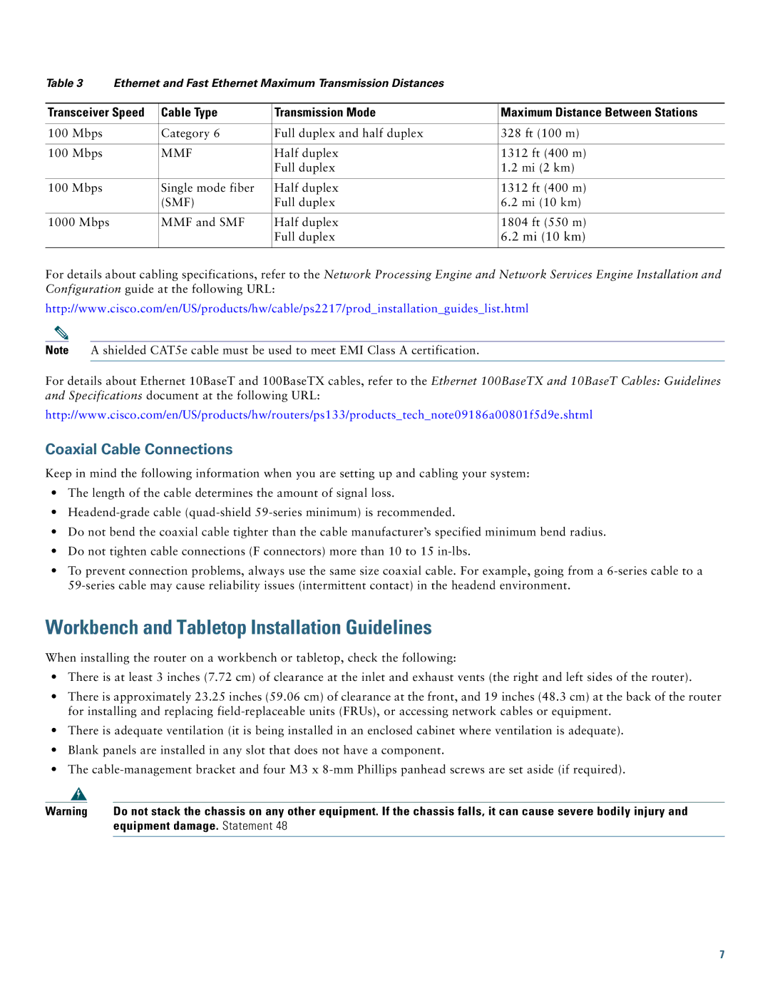
Table 3 | Ethernet and Fast Ethernet Maximum Transmission Distances |
| ||
|
|
|
| |
Transceiver Speed | Cable Type | Transmission Mode | Maximum Distance Between Stations | |
|
|
|
|
|
100 Mbps |
| Category 6 | Full duplex and half duplex | 328 ft (100 m) |
|
|
|
|
|
100 Mbps |
| MMF | Half duplex | 1312 ft (400 m) |
|
|
| Full duplex | 1.2 mi (2 km) |
|
|
|
|
|
100 Mbps |
| Single mode fiber | Half duplex | 1312 ft (400 m) |
|
| (SMF) | Full duplex | 6.2 mi (10 km) |
|
|
|
|
|
1000 Mbps |
| MMF and SMF | Half duplex | 1804 ft (550 m) |
|
|
| Full duplex | 6.2 mi (10 km) |
|
|
|
|
|
For details about cabling specifications, refer to the Network Processing Engine and Network Services Engine Installation and Configuration guide at the following URL:
http://www.cisco.com/en/US/products/hw/cable/ps2217/prod_installation_guides_list.html
Note A shielded CAT5e cable must be used to meet EMI Class A certification.
For details about Ethernet 10BaseT and 100BaseTX cables, refer to the Ethernet 100BaseTX and 10BaseT Cables: Guidelines and Specifications document at the following URL:
http://www.cisco.com/en/US/products/hw/routers/ps133/products_tech_note09186a00801f5d9e.shtml
Coaxial Cable Connections
Keep in mind the following information when you are setting up and cabling your system:
•The length of the cable determines the amount of signal loss.
•
•Do not bend the coaxial cable tighter than the cable manufacturer’s specified minimum bend radius.
•Do not tighten cable connections (F connectors) more than 10 to 15
•To prevent connection problems, always use the same size coaxial cable. For example, going from a
Workbench and Tabletop Installation Guidelines
When installing the router on a workbench or tabletop, check the following:
•There is at least 3 inches (7.72 cm) of clearance at the inlet and exhaust vents (the right and left sides of the router).
•There is approximately 23.25 inches (59.06 cm) of clearance at the front, and 19 inches (48.3 cm) at the back of the router for installing and replacing
•There is adequate ventilation (it is being installed in an enclosed cabinet where ventilation is adequate).
•Blank panels are installed in any slot that does not have a component.
•The
Warning | Do not stack the chassis on any other equipment. If the chassis falls, it can cause severe bodily injury and |
| equipment damage. Statement 48 |
|
|
7