Installation
Inserting the Chassis into the Rack
Step 2 Slide the chassis into the rack until the front flange is flat against the cage nuts. (Cage nuts are not needed in round hole racks.)
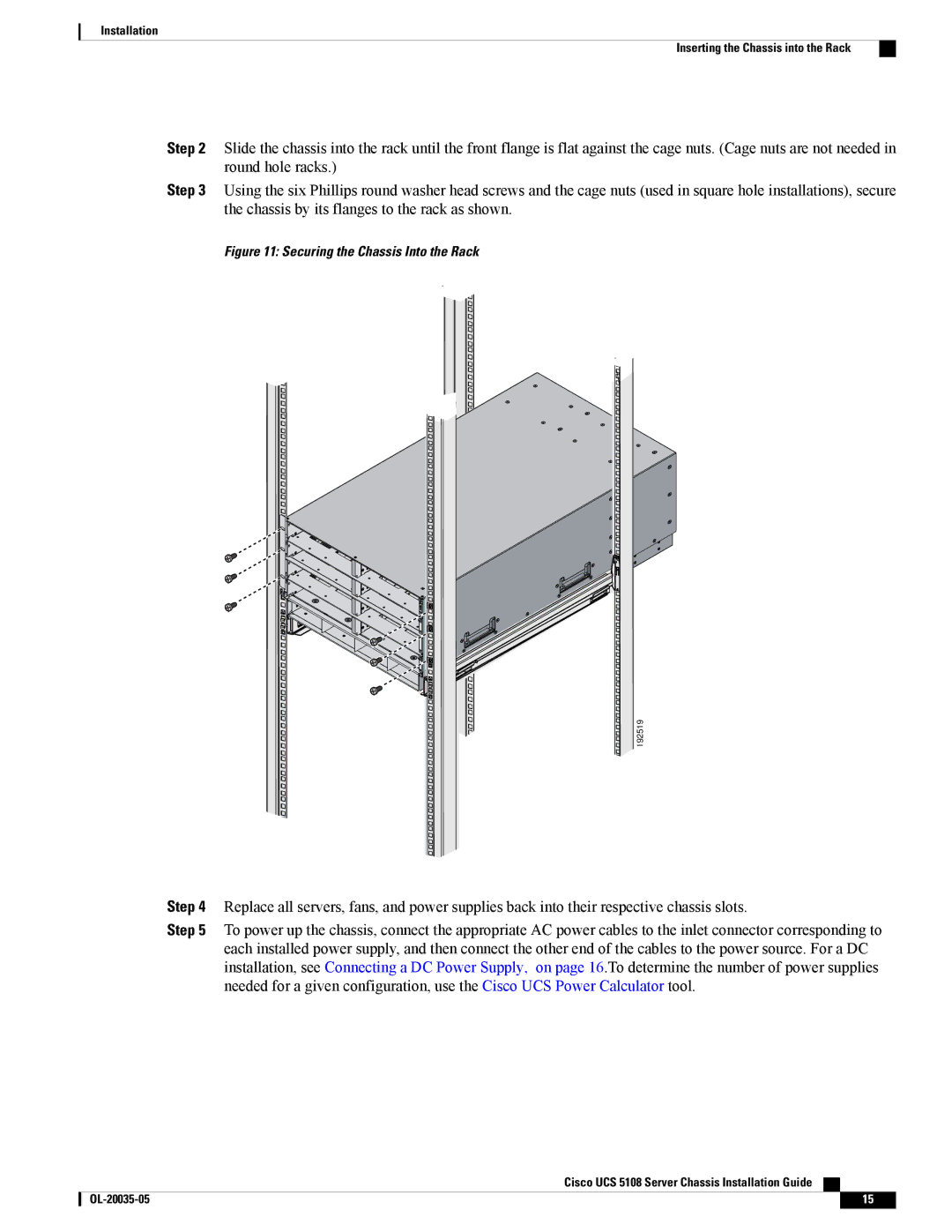
Step 3 Using the six Phillips round washer head screws and the cage nuts (used in square hole installations), secure the chassis by its flanges to the rack as shown.
Figure 11: Securing the Chassis Into the Rack
192519
Step 4 Replace all servers, fans, and power supplies back into their respective chassis slots.
Step 5 To power up the chassis, connect the appropriate AC power cables to the inlet connector corresponding to each installed power supply, and then connect the other end of the cables to the power source. For a DC installation, see Connecting a DC Power Supply, on page 16.To determine the number of power supplies needed for a given configuration, use the Cisco UCS Power Calculator tool.
Cisco UCS 5108 Server Chassis Installation Guide
15 |