Installation
Installing the Rails
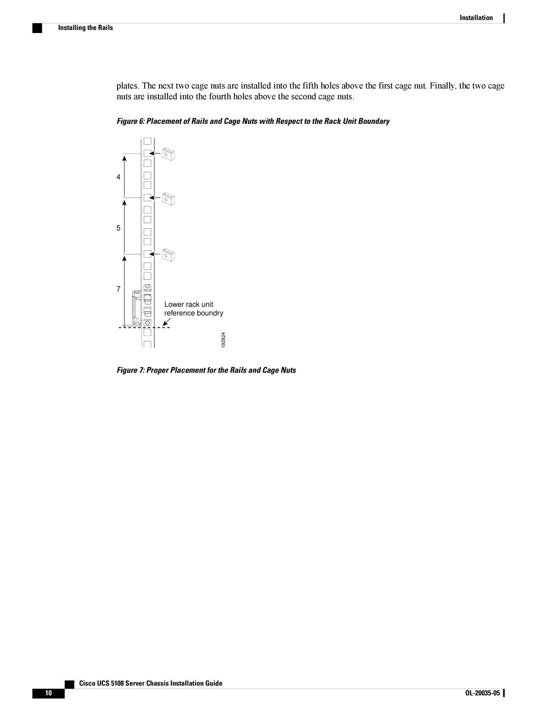
plates. The next two cage nuts are installed into the fifth holes above the first cage nut. Finally, the two cage nuts are installed into the fourth holes above the second cage nuts.
Figure 6: Placement of Rails and Cage Nuts with Respect to the Rack Unit Boundary
4
5
7
Lower rack unit reference boundry
192824
Figure 7: Proper Placement for the Rails and Cage Nuts
Cisco UCS 5108 Server Chassis Installation Guide
10 |