Installation
Cabling Considerations for Fabric Port Channels
Step 7 Replace the terminal cover as shown. This cover should always be in place when power is applied to the terminals.
Step 8 Connect the other end of the power wires to a
Step 9 Set the DC disconnect switch in the circuit to ON.
Caution In a system with multiple power supplies, connect each power supply to a separate DC power source. In the event of a power source failure, if the second source is still available, it can maintain system operation.
Step 10 Verify power supply operation by checking the power supply's
•The LED labeled INPUT OK is green.
•The LED labeled OUTPUT FAIL is not lit.
Step 11 Check the power supply and system status from the UCS console by entering the show system command or the show power command, do using the GUI. For more information on these commands, refer to the command reference for your software.
Cabling Considerations for Fabric Port Channels
When you configure the links between the Cisco UCS 2200 Series FEX and a Cisco UCS 6200 series fabric interconnect in fabric port channel mode, the available VIF namespace on the adapter varies depending on where the FEX uplinks are connected to the fabric interconnect ports.
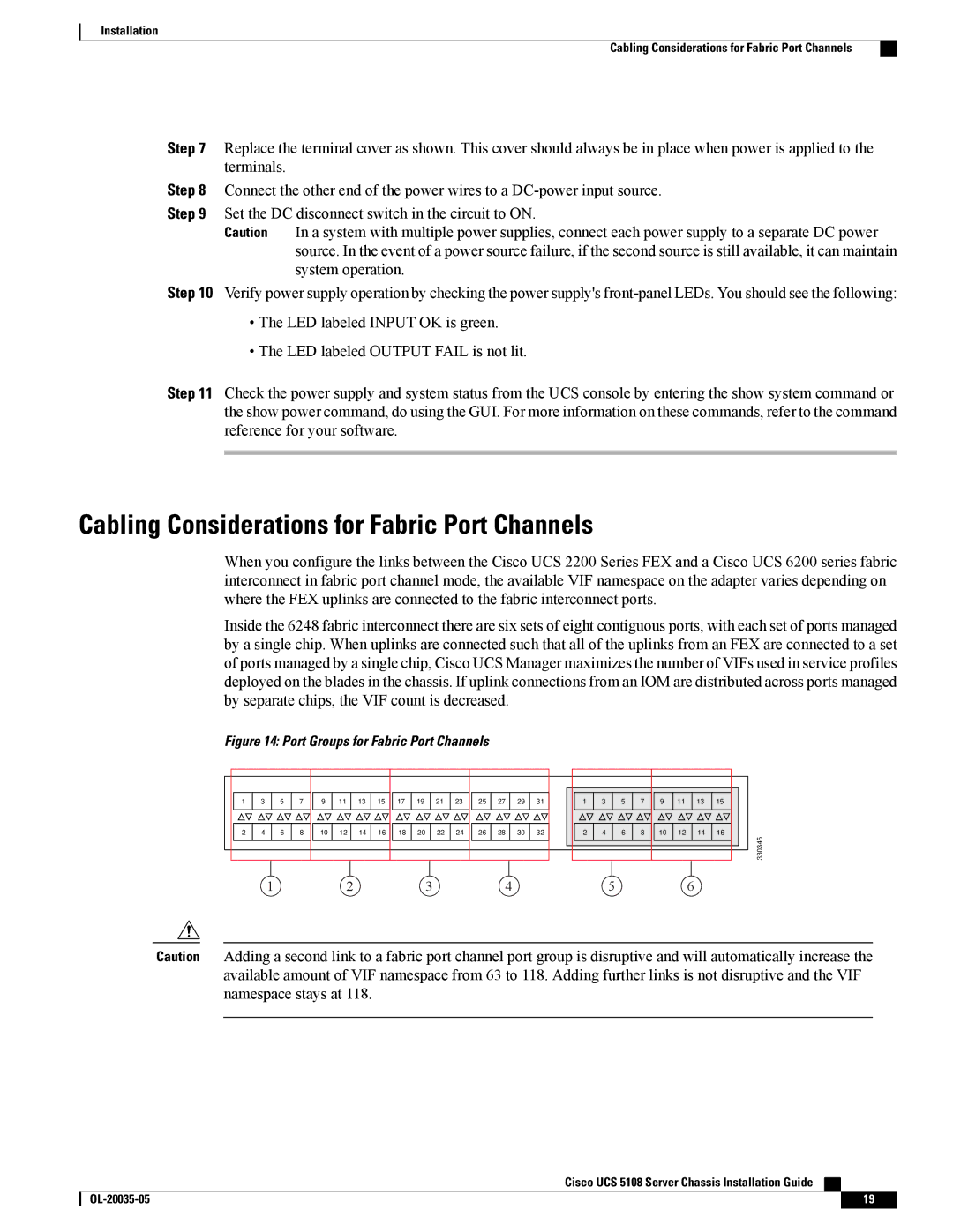
Inside the 6248 fabric interconnect there are six sets of eight contiguous ports, with each set of ports managed by a single chip. When uplinks are connected such that all of the uplinks from an FEX are connected to a set of ports managed by a single chip, Cisco UCS Manager maximizes the number of VIFs used in service profiles deployed on the blades in the chassis. If uplink connections from an IOM are distributed across ports managed by separate chips, the VIF count is decreased.
Figure 14: Port Groups for Fabric Port Channels
1 | 3 | 5 | 7 | 9 | 11 | 13 | 15 | 17 | 19 | 21 | 23 | 25 | 27 | 29 | 31 | 1 | 3 | 5 | 7 | 9 | 11 | 13 | 15 |
2 | 4 | 6 | 8 | 10 | 12 | 14 | 16 | 18 | 20 | 22 | 24 | 26 | 28 | 30 | 32 | 2 | 4 | 6 | 8 | 10 | 12 | 14 | 16 |
|
|
|
|
|
|
|
|
|
|
|
|
|
|
|
|
|
|
|
|
|
|
| 330345 |
1 | 2 | 3 | 4 | 5 | 6 |
Caution Adding a second link to a fabric port channel port group is disruptive and will automatically increase the available amount of VIF namespace from 63 to 118. Adding further links is not disruptive and the VIF namespace stays at 118.
Cisco UCS 5108 Server Chassis Installation Guide
19 |