Installation
Connecting a DC Power Supply
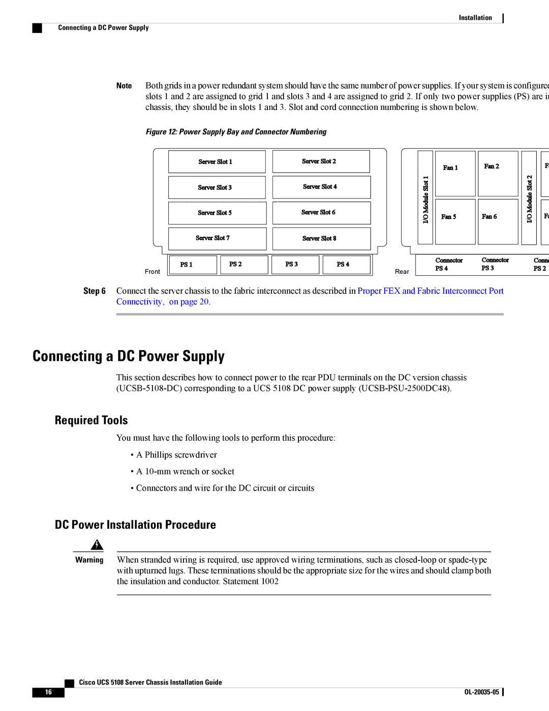
Note Both grids in a power redundant system should have the same number of power supplies. If your system is configured slots 1 and 2 are assigned to grid 1 and slots 3 and 4 are assigned to grid 2. If only two power supplies (PS) are in chassis, they should be in slots 1 and 3. Slot and cord connection numbering is shown below.
Figure 12: Power Supply Bay and Connector Numbering
Front
Server Slot 1
Server Slot 3
Server Slot 5
Server Slot 7
PS 1 |
| PS 2 |
|
|
|
Server Slot 2
Server Slot 4
Server Slot 6
Server Slot 8
PS 3 |
| PS 4 |
|
|
|
I/O Module Slot 1
Rear
Fan 1
Fan 5
Connector PS 4
Fan 2
Fan 6
Connector PS 3
I/O Module Slot 2
F
Fa
Conne PS 2
Step 6 Connect the server chassis to the fabric interconnect as described in Proper FEX and Fabric Interconnect Port Connectivity, on page 20.
Connecting a DC Power Supply
This section describes how to connect power to the rear PDU terminals on the DC version chassis
Required Tools
You must have the following tools to perform this procedure:
•A Phillips screwdriver
•A
•Connectors and wire for the DC circuit or circuits
DC Power Installation Procedure
Warning When stranded wiring is required, use approved wiring terminations, such as
| Cisco UCS 5108 Server Chassis Installation Guide |
16 |