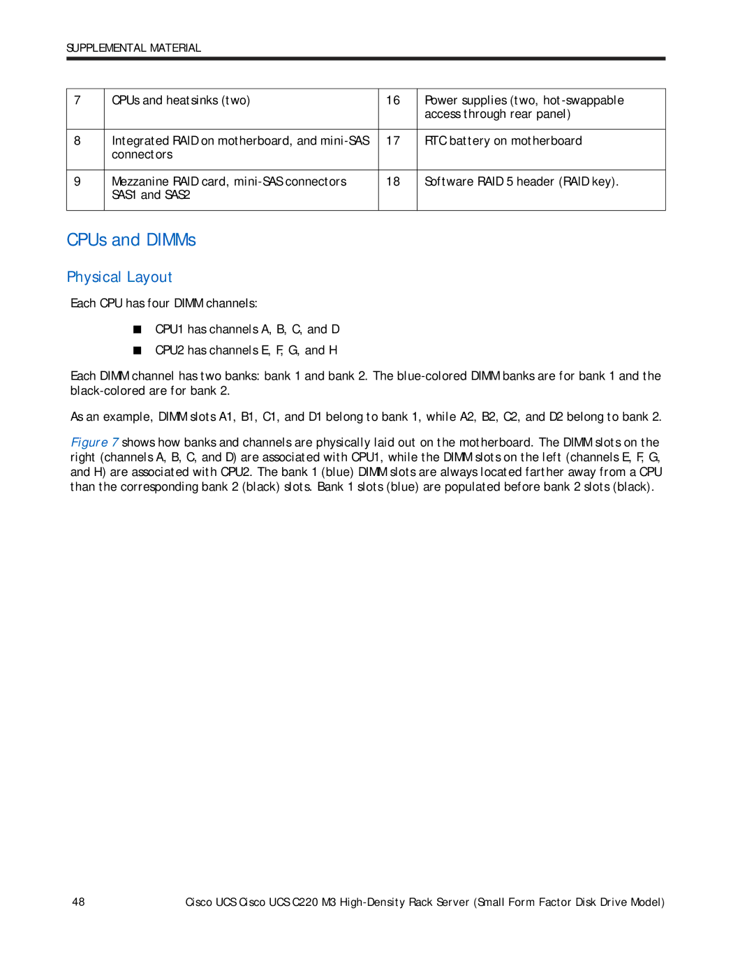
SUPPLEMENTAL MATERIAL
7 | CPUs and heatsinks (two) | 16 | Power supplies (two, |
|
|
| access through rear panel) |
|
|
|
|
8 | Integrated RAID on motherboard, and | 17 | RTC battery on motherboard |
| connectors |
|
|
|
|
|
|
9 | Mezzanine RAID card, | 18 | Software RAID 5 header (RAID key). |
| SAS1 and SAS2 |
|
|
|
|
|
|
CPUs and DIMMs
Physical Layout
Each CPU has four DIMM channels:
■CPU1 has channels A, B, C, and D
■CPU2 has channels E, F, G, and H
Each DIMM channel has two banks: bank 1 and bank 2. The
As an example, DIMM slots A1, B1, C1, and D1 belong to bank 1, while A2, B2, C2, and D2 belong to bank 2.
Figure 7 shows how banks and channels are physically laid out on the motherboard. The DIMM slots on the right (channels A, B, C, and D) are associated with CPU1, while the DIMM slots on the left (channels E, F, G, and H) are associated with CPU2. The bank 1 (blue) DIMM slots are always located farther away from a CPU than the corresponding bank 2 (black) slots. Bank 1 slots (blue) are populated before bank 2 slots (black).
48 | Cisco UCS Cisco UCS C220 M3 |