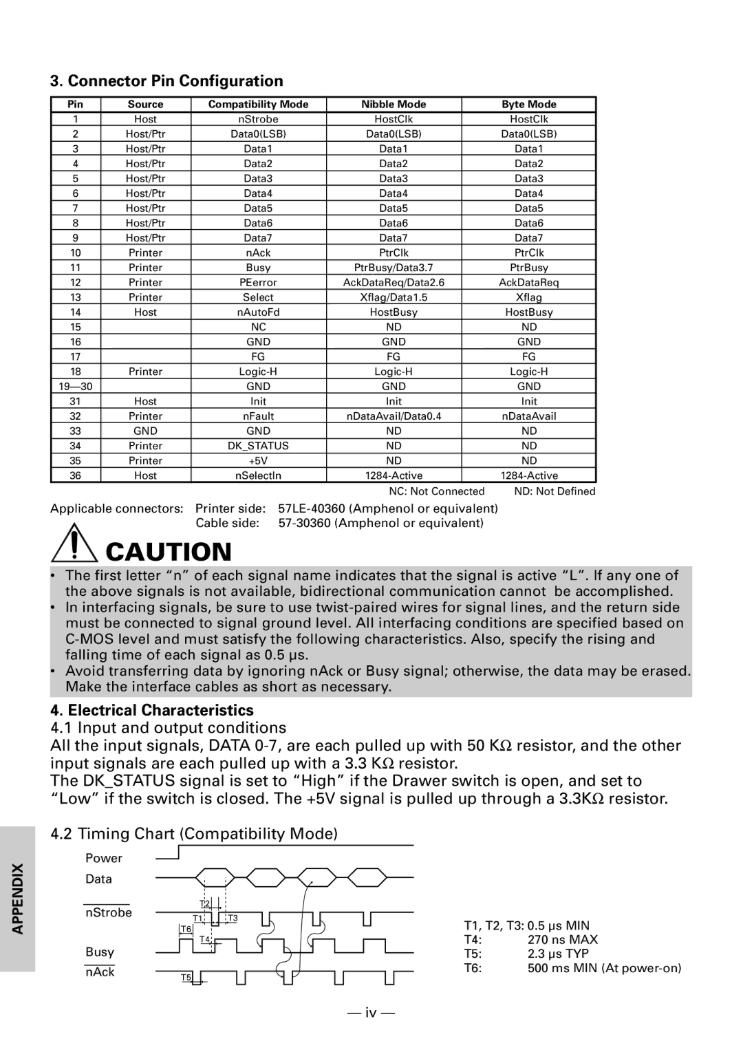
3. Connector Pin Configuration
Pin | Source | Compatibility Mode | Nibble Mode |
| Byte Mode |
1 | Host | nStrobe | HostClk |
| HostClk |
2 | Host/Ptr | Data0(LSB) | Data0(LSB) |
| Data0(LSB) |
3 | Host/Ptr | Data1 | Data1 |
| Data1 |
4 | Host/Ptr | Data2 | Data2 |
| Data2 |
5 | Host/Ptr | Data3 | Data3 |
| Data3 |
6 | Host/Ptr | Data4 | Data4 |
| Data4 |
7 | Host/Ptr | Data5 | Data5 |
| Data5 |
8 | Host/Ptr | Data6 | Data6 |
| Data6 |
9 | Host/Ptr | Data7 | Data7 |
| Data7 |
10 | Printer | nAck | PtrClk |
| PtrClk |
11 | Printer | Busy | PtrBusy/Data3.7 |
| PtrBusy |
12 | Printer | PEerror | AckDataReq/Data2.6 |
| AckDataReq |
13 | Printer | Select | Xflag/Data1.5 |
| Xflag |
14 | Host | nAutoFd | HostBusy |
| HostBusy |
15 |
| NC | ND |
| ND |
16 |
| GND | GND |
| GND |
17 |
| FG | FG |
| FG |
18 | Printer |
| |||
| GND | GND |
| GND | |
31 | Host | Init | Init |
| Init |
32 | Printer | nFault | nDataAvail/Data0.4 |
| nDataAvail |
33 | GND | GND | ND |
| ND |
34 | Printer | DK_STATUS | ND |
| ND |
35 | Printer | +5V | ND |
| ND |
36 | Host | nSelectIn |
| ||
|
|
| NC: Not Connected | ND: Not Defined | |
Applicable connectors: Printer side:
Cable side:
CAUTION
•The first letter “n” of each signal name indicates that the signal is active “L”. If any one of the above signals is not available, bidirectional communication cannot be accomplished.
•In interfacing signals, be sure to use
•Avoid transferring data by ignoring nAck or Busy signal; otherwise, the data may be erased. Make the interface cables as short as necessary.
4. Electrical Characteristics
4.1 Input and output conditions
All the input signals, DATA
The DK_STATUS signal is set to “High” if the Drawer switch is open, and set to “Low” if the switch is closed. The +5V signal is pulled up through a 3.3KΩ resistor.
4.2 Timing Chart (Compatibility Mode)
APPENDIX
Power
Data
|
|
|
| T2 |
|
|
| |
nStrobe |
|
|
|
| T3 | |||
|
|
|
|
|
| |||
| T1 |
| ||||||
|
|
|
| |||||
|
| T6 |
|
|
|
|
|
|
|
|
|
| T4 |
|
| ||
|
|
|
|
|
|
|
|
|
Busy
nAck T5
T1, T2, T3: 0.5 | µs MIN | |
T4: | 270 ns MAX | |
T5: | 2.3 | µs TYP |
T6: | 500 ms MIN (At | |
— iv —