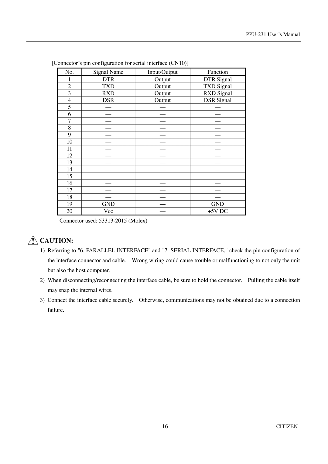
[Connector’s pin configuration for serial interface (CN10)]
No. | Signal Name | Input/Output | Function |
1 | DTR | Output | DTR Signal |
2 | TXD | Output | TXD Signal |
3 | RXD | Output | RXD Signal |
4 | DSR | Output | DSR Signal |
5 | — | — | — |
6 | — | — | — |
7 | — | — | — |
8 | — | — | — |
9 | — | — | — |
10 | — | — | — |
11 | — | — | — |
12 | — | — | — |
13 | — | — | — |
14 | — | — | — |
15 | — | — | — |
16 | — | — | — |
17 | — | — | — |
18 | — | — | — |
19 | GND | — | GND |
20 | Vcc | — | +5V DC |
Connector used:
![]() CAUTION:
CAUTION:
1)Referring to "6. PARALLEL INTERFACE" and "7. SERIAL INTERFACE," check the pin configuration of the interface connector and cable. Wrong wiring could cause trouble or malfunctioning to not only the unit but also the host computer.
2)When disconnecting/reconnecting the interface cable, be sure to hold the connector. Pulling the cable itself may snap the internal wires.
3)Connect the interface cable securely. Otherwise, communications may not be obtained due to a connection failure.
16 | CITIZEN |
