Manuals
/
Citizen
/
Computer Equipment
/
Printer
Citizen
PPU-231
manual
Japanese
Models:
PPU-231
1
95
100
100
Download
100 pages
6.74 Kb
92
93
94
95
96
97
98
99
Specifications
Electrical Characteristics
Install
Timing Chart
Input and Output Signals
Error Detection
Connecting the AC Adapter
Maintenance
Connectors Pin Configuration
Commands List
Page 95
Image 95
PPU-231
User’s Manual
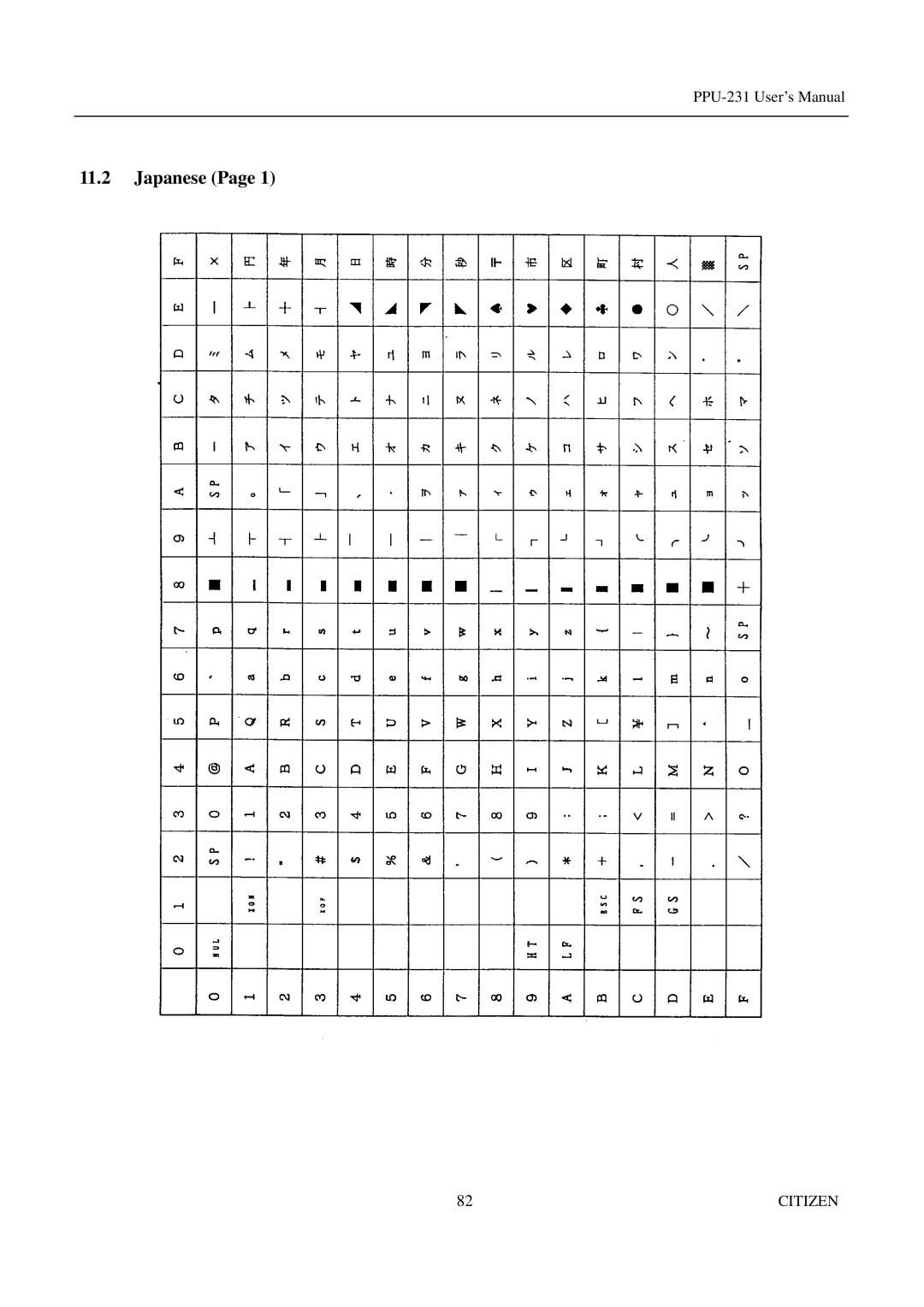
11.2
Japanese (Page 1)
82
CITIZEN
Page 94
Page 96
Page 95
Image 95
Page 94
Page 96
Contents
Line Thermal Printer
Declaration of Conformity
Important Safety Instructions
Lärmemission kleiner 70dBA
Wichtige Sicherheitsanweisungen
Citizen
Be Sure to Observe
Safety Precautions
Citizen
Precautions for Installation
Precautions for Handling
Daily Maintenance
Contents
DIP Switch Setting
Appendix
Unpacking
Features
Outline
PPU series Printer/Presenter unit
Basic Specifications
Model Classifications
Options PHU series Paper holding unit
31AD series Power supply unit
PMU series Printer mechanism unit
Miscellaneous
PRU series Presenter unit
BD2 series Control PCB with accessories
ESC/POS
Basic Specifications
Printing Position
Paper Specifications
Recommended Paper
Printing Head and Paper Cutter Layout
PPU Printer/Presenter Unit
Outer Appearance and Component Parts
Citizen
Optional PHU Paper Holding Unit
Operation
Connecting the AC Adapter
Using the Power Connector
GND
Connecting a Power Cable to the Control PCB
CN1
Connecting the Interface Cable
ACK
STB
Busy
DSR
DTR
TXD
RXD
Inserting the Paper
How to Remove Remaining Paper Roll
Eliminating a Jam in the Printer Mechanism
Eliminating the Paper Jam
Eliminating a Jam in the Presenter
Paper End Function
Feed Switch Function
Releasing a Locked Cutter
PNE
Connecting the PHU Paper Holding Unit
Paper Near End Function When Using the PHU
CN5
Presenter Control
Auto-Loading Function
Self-Print Function
Location of DIP Switch
DIP Switch Setting
Baud rate and parity setting
DIP Switch Function
DIP switch 1 DS1
DIP switch 2 DS2
Print density
Strobe Twisted Pair GND Data ACK Busy Reset Fault Frame GND
Specifications
Connectors Pin Configuration
ACK, BUSY, STROBE, FAULT, PE, Reset
Strobe
Input and Output Signals
Input and Output Signals
Electrical Characteristics
Buffering
Timing Chart
Data Receiving Control
Serial Interface
Input and Output Signals
Error Detection
Data Configuration
Output TXD, DTR Printer Side
Electrical Characteristics RS-232C Circuit
Power Connector
Maintenance and Service
Print Control Functions
Commands List
1DH 3AH
Description of Items
Command Details
ESC D
Details
ESC SP
ESC
Lprint CHR$ &HA
ESC
ESC %
ESC & s n P s × a m n +1
Citizen
ESC ∗ m n1 N2 d k
Example Sample Program
ESC − n
ESC 3 n
ESC =
52CITIZEN
ESC D n NUL
ESC E
ESC E
ESC G
ESC R
Condition Canceling 90-right- turned Characters
Position
ESC c Parallel Interface Only
ESC d
ESC c
ESC When Using Auto Cutter
ESC m When Using Auto Cutter
ESC t
XON/XOFF
ESC Serial Interface Only
Inverted printing means printing the line at 180turned
ESC ¥
ESC $ n1
ESC $
Type Only
UPC-A
GS k n
UPC-A UPC-E JAN13 EAN JAN 8 EAN Code
Codabar NW-7
ITF
JAN-13EAN
JAN-8EAN
CODE39
Code Btestcode A123
Test
UPC-A
GS w
GS h n
Specify before the GS k command
GS H
GS f n
GS ∗ n1 N2 d n1 × n2 ×
Sample Program Print Results
203 DPI Double wide mode
Lprint CHR$
GS n1 n2 n3
International
Character Codes Table
Japanese
International Character Code Table
Appendix 1. Block Diagram
Unit mm
Appendix 2. Outline Drawing for PPU
Appendix 3. Outline Drawing for PHU
Top
Page
Image
Contents