6. REMOVING THE MAIN UNIT
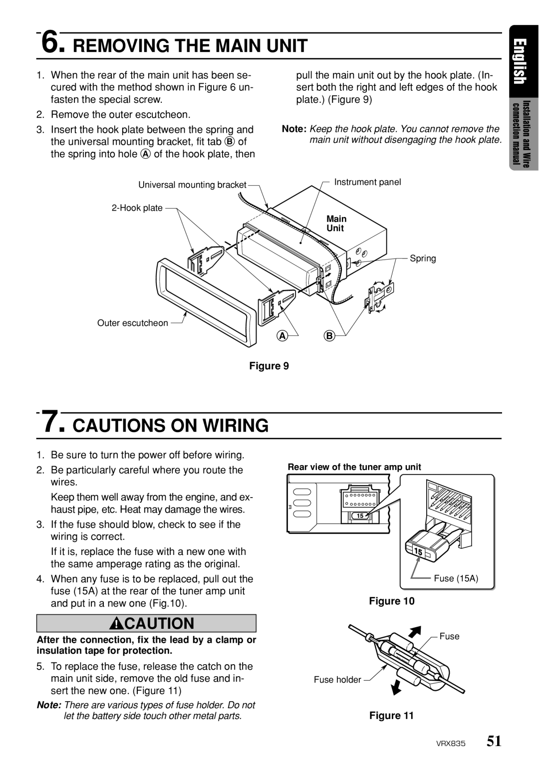
1. | When the rear of the main unit has been se- | pull the main unit out by the hook plate. (In- |
| cured with the method shown in Figure 6 un- | sert both the right and left edges of the hook |
| fasten the special screw. | plate.) (Figure 9) |
2. | Remove the outer escutcheon. |
|
3. | Insert the hook plate between the spring and | Note: Keep the hook plate. You cannot remove the |
| the universal mounting bracket, fit tab B of | main unit without disengaging the hook plate. |
the spring into hole A of the hook plate, then
Universal mounting bracket | Instrument panel |
| |
| |
| Main |
| Unit |
| Spring |
Outer escutcheon ![]()
A B
Figure 9
English connectionmanual Installationand Wire
7. CAUTIONS ON WIRING
1.Be sure to turn the power off before wiring.
2.Be particularly careful where you route the wires.
Keep them well away from the engine, and ex- haust pipe, etc. Heat may damage the wires.
3.If the fuse should blow, check to see if the wiring is correct.
If it is, replace the fuse with a new one with the same amperage rating as the original.
4.When any fuse is to be replaced, pull out the fuse (15A) at the rear of the tuner amp unit and put in a new one (Fig.10).
Rear view of the tuner amp unit
Fuse (15A)
Figure 10
![]() CAUTION
CAUTION
After the connection, fix the lead by a clamp or insulation tape for protection.
5.To replace the fuse, release the catch on the main unit side, remove the old fuse and in- sert the new one. (Figure 11)
Note: There are various types of fuse holder. Do not let the battery side touch other metal parts.
Fuse
Fuse holder ![]()
Figure 11
VRX835 51
