Purple/Black
2
Purple
1
Green/Black | 8 |
| |
Blue/White | 0 |
| |
Green | 7 |
| |
Brawn | (∗1 |
| |
Glay | 3 |
| |
¡ | |
| |
Glay/Black | 4 |
| |
Orange/White | ! |
| |
White/Black | 6 |
| |
Red | @ |
| |
White | 5 |
| |
Yellow | 9 |
| |
) |
|
Black | # |
|
![]() *
* ![]()
English connectionmanual Installationand Wire
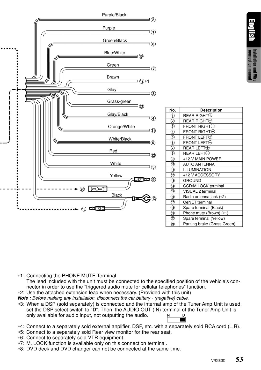
No. | Description |
1 | REAR RIGHT+ |
2 | REAR RIGHT- |
3 | FRONT RIGHT+ |
4 | FRONT RIGHT- |
5 | FRONT LEFT+ |
6 | FRONT LEFT- |
7 | REAR LEFT+ |
8 | REAR LEFT- |
9 | +12 V MAIN POWER |
0 | AUTO ANTENNA |
! | ILLUMINATION |
@ | +12 V ACCESSORY |
# | GROUND |
$ | CCD/M.LOCK terminal |
% | VISUAL 2 terminal |
¥ | Radio antenna jack (∗2) |
& | CeNET terminal |
* | Spare terminal (Black) |
( | Phone mute (Brown) (∗1) |
) | Spare terminal (Yellow) |
¡ | Parking brake |
∗1: Connecting the PHONE MUTE Terminal
The lead included with the unit must be connected to the specified position of the vehicle’s con- nector in order to use the “triggered audio mute for cellular telephones” function.
∗2: Use the attached extension lead when necessary. (Provided with this unit)
Note : Before making any installation, disconnect the car battery - (negative) cable.
∗3: When a DSP (sold separately) is connected and the internal amp of the Tuner Amp Unit is used, set the DSP select switch to “D”. Then, the AUDIO OUT (IN) terminal of the Tuner Amp Unit is
only available for audio input, not outputting the audio. | N | D |
|
|
|
∗4: Connect to a separately sold external anplifier, DSP, etc. with a separately sold RCA cord (L,R).
∗5: Connect to a separately sold Rear view monitor for the rear seat.
∗6: Connect to separately sold VTR equipment.
∗7: M. LOCK function is available only on this connection terminal.
∗8: DVD deck and DVD changer can not be connected at the same time.
VRX835 53