Maintenance and Service Guide
Page
Contents
Removal and Replacement Procedures
Removal and Replacement Preliminaries
Illustrated Parts Catalog
Screw Listing Index
Product Description
Key
Models
Key Description Options
Compaq Evo Notebook N1000 Models
220 Germany 470036-635
470036-743
Nafta
N1000 200 Brazil 470038-304
470036-744
470038-793
Compaq Presario 1500 Models
470036-786
470036-785
Compaq Presario 1500 Models
Features
Maintenance and Service Guide
Clearing a Password
Power Management
Front and Right Side Components
Computer External Components
Component Function
Front and Right Side Components
Rear Panel and Left Side Components
Rear Panel and Left Side Components
Rear Panel and Left Side Components
Num lock key
Keyboard Components
Fn key
Top Components
Top Components
Top Components
Bottom Components
Bottom Components
Bottom Components
Design Overview
Computer Setup Diagnostics Utilities
Troubleshooting
Using Computer Setup
Select To Do This
File Menu
Security Menu
Selecting from the Security Menu
Advanced Menu
Selecting from the Advanced Menu
Advanced Menu
Obtaining, Saving, or Printing Configuration Information
Using Compaq Diagnostics
Obtaining, Saving, or Printing Diagnostic Test Information
Maintenance and Service Guide
Troubleshooting Flowcharts Overview
Troubleshooting Flowcharts
Flowchart Description
Power?
Flowchart 2.1 Initial Troubleshooting
Done
Flowchart 2.2 No Power, Part
Flowchart 2.3 No Power, Part
Plug directly Into AC outlet Power LED On? Done
Flowchart 2.4 No Power, Part
Flowchart 2.5 No Power, Part
Flowchart 2.6 No Video, Part
From Flowchart No Video, Part
Flowchart 2.7 No Video, Part
O board Backplane board Switch box
Flowchart 2.8 Nonfunctioning Docking Station if applicable
Flowchart 2.9 No Operating System OS Loading
CD?
Flowchart 2.10 No OS Loading from Hard Drive, Part
Flowchart 2.11 No OS Loading from Hard Drive, Part
Flowchart 2.12 No OS Loading from Hard Drive, Part
Flowchart 2.13 No OS Loading from Diskette Drive
Flowchart 2.14 No OS Loading from CD- or DVD-ROM Drive
Undock
Flowchart 2.15 No Audio, Part
Flowchart 2.16 No Audio, Part
Cmos
Flowchart 2.17 Nonfunctioning Device
OK?
Flowchart 2.18 Nonfunctioning Keyboard
Flowchart 2.19 Nonfunctioning Pointing Device
Flowchart 2.20 No Network or Modem Connection
Serial Number Location
Illustrated Parts Catalog
Computer System Major Components
Computer System Major Components
Spare Part
Spare Parts Computer System Major Components
Description Number Displays
Computer System Major Components
LED cover
Computer System Major Components
Item Description Number
Computer System Major Components
Diskette drives
Description Number Miscellaneous Cable Kit, includes
Top cover
Palm rests
Computer System Major Components
Heat spreaders
Description Number
Computer System Major Components
Fan
Speaker assembly
Description Number Processors
Charger board
Computer System Major Components
Mini PCI communications boards
Disk cell RTC battery, 3 volt, 36 MAh, Li ion
Battery packs
Description Number Hard drives
Miscellaneous Plastics/Hardware Kit Components
Miscellaneous Plastics/Hardware Kit
Description
Miscellaneous Cable Kit Components
Miscellaneous Cable Kit
Item Description
Miscellaneous Cable Kit Components Spare Part Number
Mass Storage Devices
Mass Storage Devices
Mass Storage Devices
Spare Parts Miscellaneous not illustrated
Miscellaneous
Tools Required
Removal and Replacement Preliminaries
Plastic Parts
Service Considerations
Preventing Damage to Removable Drives
Preventing Electrostatic Damage
Packaging and Transporting Precautions
Workstation Precautions
Grounding Equipment and Methods
Material Use Voltage Protection Level
Typical Electrostatic Voltage Levels
Static-Shielding Materials
Relative Humidity Event 10% 40% 55%
Removal and Replacement Procedures
Serial Number
Disassembly Sequence Chart
Disassembly Sequence Chart
Section Description # of Screws Removed
Preparing the Computer for Disassembly
Releasing the Battery Pack
Battery Packs Spare Part Number Information
Removing the Battery Bezel
Removing the Optical Drive Screws
Optical Drives Spare Part Number Information
Reverse the preceding procedures to install a optical drive
Spare Part Number Information
Hard Drives
Removing the Hard Drive
Removing the Hard Drive Bracket
Memory Expansion Board
Computer Feet
Memory Expansion Boards
10. Removing the Memory Expansion Compartment Cover
Mini PCI Communication Boards Spare Part Number Information
Mini PCI Communications Board
12. Removing the Mini PCI Communications Slot Cover
13. Removing a Mini PCI Communications Board
Disk Cell RTC Battery Spare Part Number Information
Disk Cell RTC Battery
15. Removing the Connector Cover
Connector Cover
LED Cover Spare Part Number Information
LED Cover
Reverse the preceding procedures to install the LED cover
Keyboards Spare Part Number Information
Keyboard
18. Releasing the Keyboard
19. Disconnecting the Keyboard-to-TouchPad Cable
Heat Spreaders Spare Part Number Information
Heat Spreader
20. Removing the Heat Spreader Screws
21. Removing the Heat Spreader
Processors Spare Part Number Information
Processor
Reverse the preceding procedures to install the processor
Displays Spare Part Number Information
Display
Removal and Replacement Procedures
24. Removing the Display
25. Removing the Display Hinge Covers
26. Installing the Display Screws
Palm Rests Spare Part Number Information
Palm Rest
27. Removing the Palm Rest Screws
28. Removing the Palm Rest
29. Disconnecting the Keyboard-to-TouchPad Cable
Diskette Drives Spare Part Number Information
Diskette Drive
31. Removing the Diskette Drive Cable
TouchPad Components Spare Part Number Information
TouchPad Components
32. Removing the TouchPad-to-TouchButton Board Cable
33. Removing the TouchPad Components on TouchPad Models
Maintenance and Service Guide
35. Removing the TouchPad Components on Dual Stick Models
36. Removing the Display Release Assembly
Display Release Assembly
Charger Board Spare Part Number Information
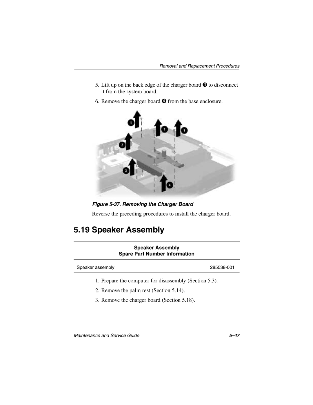
Charger Board
Speaker Assembly Spare Part Number Information
Speaker Assembly
38. Removing the Speaker Assembly
Top Cover Spare Part Number Information
Top Cover
39. Removing the Top Cover Screws
40. Removing the Top Cover and Microphone
Reverse the preceding procedures to install the top cover
Fan Spare Part Number Information
21 Fan
Reverse the preceding procedures to install the fan
System Board Spare Part Number Information
System Board
43. Removing the Optical Drive Alignment Rails
44. Removing the System Board Screws
Reverse the preceding procedures to install the system board
Modem Cable
Reverse the preceding procedures to install the modem cable
Weight varies by notebook configuration
Dimensions
Temperature
Stand-alone power requirements
Relative humidity noncondensing
Vibration
Shock
Inch SXGA+, TFT Display
Inch XGA, TFT Display
Total power Consumption
Interface type
Logical configuration
40 GB 30 GB 20 GB User capacity per
Drive1 Drive height Drive width
Speed Transfer rate
40 GB 30 GB 20 GB Physical configuration
Buffer size3
Disk rotational
Diskette Drive
DVD-ROM Drive
DVD-RW Drive
Access time
Cache buffer Data transfer rate
CD-ROM Drive
Track pitch Access time
CD-RW Drive
External AC Adapter
Cell, Li ion Battery Pack
Weight
Power supply
Hardware DMA System Function
System DMA
Hardware IRQ System Function
System Interrupts
System I/O Addresses
16F Unused
VGA
Size Memory Address System Function
System Memory Map
Table A-1 RJ-45 Network Interface
Pin Signal
Table A-3 Universal Serial Bus
Table A-2 RJ-11 Modem
Table A-5 External Keyboard/Mouse
Table A-4 Video
Table A-6 Parallel
Table A-7 External Monitor
Table A-9 Microphone
Pin Signal Audio out
Pin Signal Audio
Table A-8 Stereo Speaker/Headphone
Conductor Power Cord Set
Power Cord Set Requirements
Country-Specific Requirements
Conductor Power Cord Set Requirements
Country Accredited Agency Applicable Note Number
BSI
Screw Listing
Table C-1 Torx T8 Metric 2.5 × 5.0 Screw
Color Qty Length Thread Width Silver Where used
Head
Figure C-2. TM2.5 × 5.0 Screw Locations
Figure C-3. TM2.5 × 5.0 Screw Locations
Figure C-4. TM2.5 × 5.0 Screw Locations
Figure C-5. TM2.5 × 5.0 Screw Locations
Figure C-6. TM2.5 × 5.0 Screw Locations
Figure C-7. TM2.5 × 5.0 Screw Locations
Figure C-8. TM2.5 × 5.0 Screw Locations
Figure C-9. TM2.5 × 8.0 Screw Locations
Table C-2 Torx T8 Metric 2.5 × 8.0 Screw
Figure C-10. TM2.5 × 8.0 Screw Locations
Figure C-11. PM3.0 × 3.0 Screw Locations
Table C-3 Phillips Metric 3.0 × 3.0 Screw
Head Color Qty Length Thread Width
Table C-4 Phillips Metric 2.5 × 4.0 Screw
Table C-5 Torx T8 Metric 2.5 × 14.0 Shoulder Screw
Color Qty Length Thread Width Silver 14.0 mm Where used
Figure C-14. TM2.5 × 9.0 Screw Locations
Table C-6 Torx T8 Metric 2.5 × 9.0 Screw
Figure C-15. PM2.0 × 4.5 Screw Locations
Table C-7 Phillips Metric 2.0 × 4.5 Screw
Index
Index-2
Index-3
Index-4
Index-5
Index-6
Index-7