9.3.1Selecting the Sync Source
Input sync selection is made using the "Sync Select” button located on the back panel. For an external sync operation, press the “Sync Select” button. For an internal sync operation, release the “Sync Select” button. This modifies the input circuitry to select the required input sync source.
9.3.2Setting the Configuration Switches
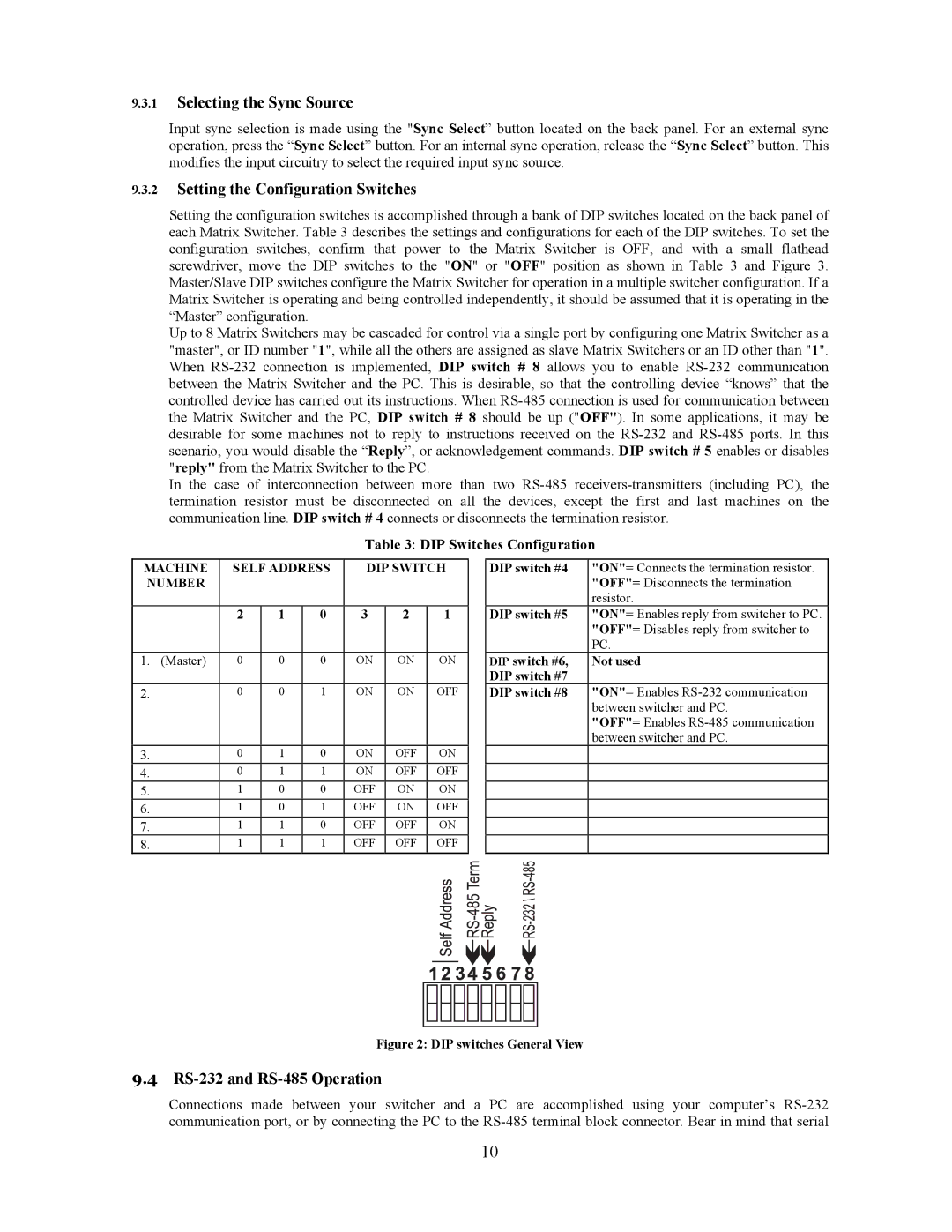
Setting the configuration switches is accomplished through a bank of DIP switches located on the back panel of each Matrix Switcher. Table 3 describes the settings and configurations for each of the DIP switches. To set the configuration switches, confirm that power to the Matrix Switcher is OFF, and with a small flathead screwdriver, move the DIP switches to the "ON" or "OFF" position as shown in Table 3 and Figure 3. Master/Slave DIP switches configure the Matrix Switcher for operation in a multiple switcher configuration. If a Matrix Switcher is operating and being controlled independently, it should be assumed that it is operating in the “Master” configuration.
Up to 8 Matrix Switchers may be cascaded for control via a single port by configuring one Matrix Switcher as a "master", or ID number "1", while all the others are assigned as slave Matrix Switchers or an ID other than "1". When
In the case of interconnection between more than two
Table 3: DIP Switches Configuration
MACHINE | SELF ADDRESS | DIP SWITCH | |||||
NUMBER |
|
|
|
|
|
| |
|
|
|
|
|
|
|
|
|
| 2 | 1 | 0 | 3 | 2 | 1 |
|
|
|
|
|
|
|
|
1. | (Master) | 0 | 0 | 0 | ON | ON | ON |
|
|
|
|
|
|
|
|
2. |
| 0 | 0 | 1 | ON | ON | OFF |
|
|
|
|
|
|
|
|
3. |
| 0 | 1 | 0 | ON | OFF | ON |
4. |
| 0 | 1 | 1 | ON | OFF | OFF |
5. |
| 1 | 0 | 0 | OFF | ON | ON |
6. |
| 1 | 0 | 1 | OFF | ON | OFF |
7. |
| 1 | 1 | 0 | OFF | OFF | ON |
8. |
| 1 | 1 | 1 | OFF | OFF | OFF |
| DIP switch #4 | "ON"= Connects the termination resistor. | |||||||
|
|
|
|
|
|
|
|
| "OFF"= Disconnects the termination |
|
|
|
|
|
|
|
|
| resistor. |
| DIP switch #5 | "ON"= Enables reply from switcher to PC. | |||||||
|
|
|
|
|
|
|
|
| "OFF"= Disables reply from switcher to |
|
|
|
|
|
|
|
|
| PC. |
| DIP switch #6, | Not used | |||||||
| DIP switch #7 |
| |||||||
| DIP switch #8 | "ON"= Enables | |||||||
|
|
|
|
|
|
|
|
| between switcher and PC. |
|
|
|
|
|
|
|
|
| "OFF"= Enables |
|
|
|
|
|
|
|
|
| between switcher and PC. |
|
|
|
|
|
|
|
|
|
|
|
|
|
|
|
|
|
|
|
|
|
|
|
|
|
|
|
|
|
|
|
|
|
|
|
|
|
|
|
|
|
|
|
|
|
|
|
|
|
|
|
|
|
|
|
|
|
|
|
|
|
|
|
|
|
|
|
|
|
|
|
|
|
|
|
|
|
|
|
|
|
|
|
|
|
|
|
|
|
|
|
|
|
|
|
|
|
|
|
|
|
|
|
|
|
|
|
|
|
|
Figure 2: DIP switches General View
9.4RS-232 and RS-485 Operation
Connections made between your switcher and a PC are accomplished using your computer’s
10