12.5Switching Malfunctions
Problem | Remedy | |
|
| |
The switcher succeeds | Malfunction in the particular source or cable assembly. | |
in switching a number | NOTE | |
of sources then fails to | ||
The most common failure mode in transferring the signal of | ||
switch one. | ||
| an audio source is a break in the connecting wire. | |
| Disconnect the source from a channel that is switching successfully and connect the | |
| suspect source to it. If the channel continues to switch successfully, then there is | |
| something wrong with the Matrix Switcher or the suspect source was not connected | |
| properly. If it does not continue to switch successfully, then there is something wrong | |
| with the source or cable assembly. Check them. | |
|
| |
The Matrix Switcher | One of the two flat cables leading from the main board to the control board may be | |
turns ON but will not | disconnected and the switch command is not being transferred to the Matrix | |
switch at all | Switcher. Check them. | |
|
|
13COMMUNICATION PROTOCOL
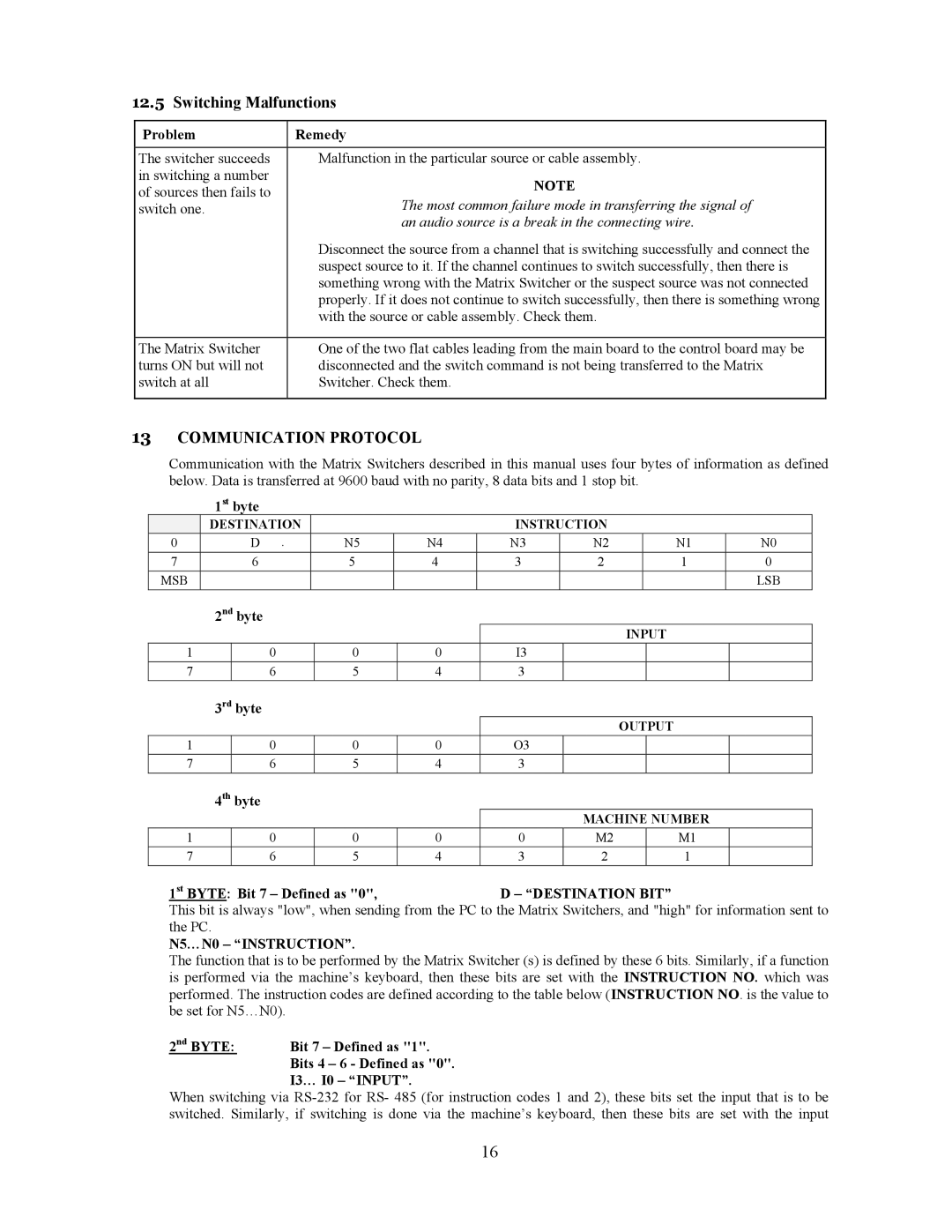
Communication with the Matrix Switchers described in this manual uses four bytes of information as defined below. Data is transferred at 9600 baud with no parity, 8 data bits and 1 stop bit.
1st byte
| DESTINATION |
|
| INSTRUCTION |
|
| |
0 | D | N5 | N4 | N3 | N2 | N1 | N0 |
7 | 6 | 5 | 4 | 3 | 2 | 1 | 0 |
MSB |
|
|
|
|
|
| LSB |
2nd byte
|
|
|
|
| INPUT | ||
1 | 0 | 0 | 0 | I3 |
|
|
|
7 | 6 | 5 | 4 | 3 |
|
|
|
3rd byte
|
|
|
|
| OUTPUT | ||
1 | 0 | 0 | 0 | O3 |
|
|
|
7 | 6 | 5 | 4 | 3 |
|
|
|
4th byte
|
|
|
|
| MACHINE NUMBER | |||
1 | 0 | 0 | 0 | 0 | M2 |
| M1 |
|
7 | 6 | 5 | 4 | 3 | 2 |
| 1 |
|
1st BYTE: Bit 7 – Defined as "0", |
| D – “DESTINATION BIT” |
|
| ||||
This bit is always "low", when sending from the PC to the Matrix Switchers, and "high" for information sent to the PC.
N5…N0 – “INSTRUCTION”.
The function that is to be performed by the Matrix Switcher (s) is defined by these 6 bits. Similarly, if a function is performed via the machine’s keyboard, then these bits are set with the INSTRUCTION NO. which was performed. The instruction codes are defined according to the table below (INSTRUCTION NO. is the value to be set for N5…N0).
Bit 7 – Defined as "1".
Bits 4 – 6 - Defined as "0".
I3… I0 – “INPUT”.
When switching via
16