No. | Feature | Function |
|
|
|
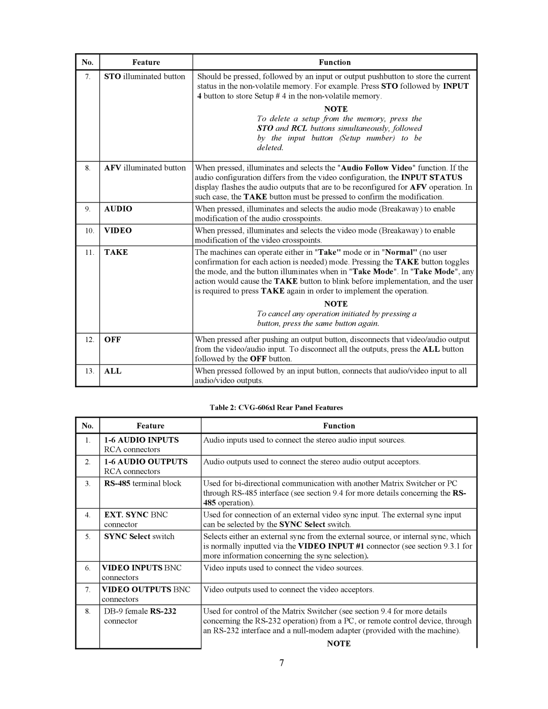
7. | STO illuminated button | Should be pressed, followed by an input or output pushbutton to store the current |
|
| status in the |
|
| 4 button to store Setup # 4 in the |
|
| NOTE |
|
| To delete a setup from the memory, press the |
|
| STO and RCL buttons simultaneously, followed |
|
| by the input button (Setup number) to be |
|
| deleted. |
|
|
|
8. | AFV illuminated button | When pressed, illuminates and selects the "Audio Follow Video" function. If the |
|
| audio configuration differs from the video configuration, the INPUT STATUS |
|
| display flashes the audio outputs that are to be reconfigured for AFV operation. In |
|
| such case, the TAKE button must be pressed to confirm the modification. |
9. | AUDIO | When pressed, illuminates and selects the audio mode (Breakaway) to enable |
|
| modification of the audio crosspoints. |
10. | VIDEO | When pressed, illuminates and selects the video mode (Breakaway) to enable |
|
| modification of the video crosspoints. |
11. | TAKE | The machines can operate either in "Take" mode or in "Normal" (no user |
|
| confirmation for each action is needed) mode. Pressing the TAKE button toggles |
|
| the mode, and the button illuminates when in "Take Mode". In "Take Mode", any |
|
| action would cause the TAKE button to blink before implementation, and the user |
|
| is required to press TAKE again in order to implement the operation. |
|
| NOTE |
|
| To cancel any operation initiated by pressing a |
|
| button, press the same button again. |
|
|
|
12. | OFF | When pressed after pushing an output button, disconnects that video/audio output |
|
| from the video/audio input. To disconnect all the outputs, press the ALL button |
|
| followed by the OFF button. |
13. | ALL | When pressed followed by an input button, connects that audio/video input to all |
|
| audio/video outputs. |
|
| Table 2: |
|
|
|
No. | Feature | Function |
|
|
|
1. | Audio inputs used to connect the stereo audio input sources. | |
| RCA connectors |
|
2. |
| Audio outputs used to connect the stereo audio output acceptors. |
| RCA connectors |
|
3. | Used for | |
|
| through |
|
| 485 operation). |
4. | EXT. SYNC BNC | Used for connection of an external video sync input. The external sync input |
| connector | can be selected by the SYNC Select switch. |
5. | SYNC Select switch | Selects either an external sync from the external source, or internal sync, which |
|
| is normally inputted via the VIDEO INPUT #1 connector (see section 9.3.1 for |
|
| more information concerning the sync selection). |
6. | VIDEO INPUTS BNC | Video inputs used to connect the video sources. |
| connectors |
|
7. | VIDEO OUTPUTS BNC | Video outputs used to connect the video acceptors. |
| connectors |
|
8.
connector | concerning the |
| an |
| NOTE |
| 7 |