10TYPICAL APPLICATIONS
10.1Basic Video-Audio Setup
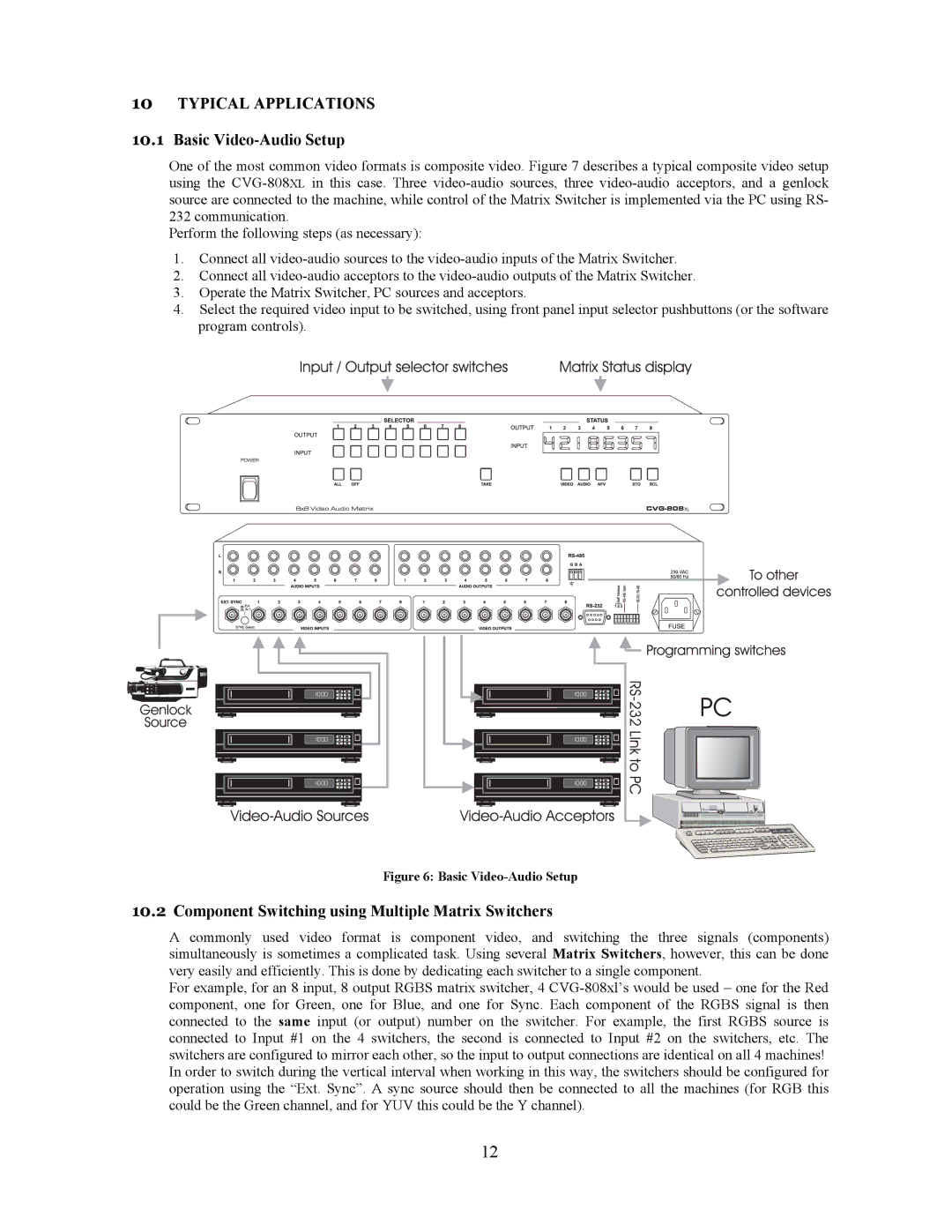
One of the most common video formats is composite video. Figure 7 describes a typical composite video setup using the CVG-808XLin this case. Three video-audio sources, three video-audio acceptors, and a genlock source are connected to the machine, while control of the Matrix Switcher is implemented via the PC using RS- 232 communication.
Perform the following steps (as necessary):
1.Connect all video-audio sources to the video-audio inputs of the Matrix Switcher.
2.Connect all video-audio acceptors to the video-audio outputs of the Matrix Switcher.
3.Operate the Matrix Switcher, PC sources and acceptors.
4.Select the required video input to be switched, using front panel input selector pushbuttons (or the software program controls).
Figure 6: Basic Video-Audio Setup
10.2Component Switching using Multiple Matrix Switchers
A commonly used video format is component video, and switching the three signals (components) simultaneously is sometimes a complicated task. Using several Matrix Switchers, however, this can be done very easily and efficiently. This is done by dedicating each switcher to a single component.
For example, for an 8 input, 8 output RGBS matrix switcher, 4 CVG-808xl’s would be used – one for the Red component, one for Green, one for Blue, and one for Sync. Each component of the RGBS signal is then connected to the same input (or output) number on the switcher. For example, the first RGBS source is connected to Input #1 on the 4 switchers, the second is connected to Input #2 on the switchers, etc. The switchers are configured to mirror each other, so the input to output connections are identical on all 4 machines! In order to switch during the vertical interval when working in this way, the switchers should be configured for operation using the “Ext. Sync”. A sync source should then be connected to all the machines (for RGB this could be the Green channel, and for YUV this could be the Y channel).
12