communication between Matrix Switchers is always via RS-485 (see example in Figure 5). The RS-232 port is either a DB-9 (9-pin port) or DB-25 (25-pin port). The cable connecting your switcher to the PC should be wired as shown in Figure 4. A 9-25 pin adapter or 9-9 pin null-modem adapter is included for your convenience. The null-modem adaptor is wired as shown in Figure 4. If using the adaptor (recommended), plug it into the PC’s serial port, and connect via a flat-cable from the other end of the adaptor to your switcher. Please keep in mind that it is not recommended to extend an RS-232 signal beyond a length of 30 feet, without the use of an RS-232 to RS-422 converter at both the PC and the switcher.
If five machines and a PC are cascaded together for example, using RS-485 interconnection, disconnect the termination resistors on all machines except the fifth (see Figure 6). For similar setup, without a PC connected on the RS-485 line, disconnect all resistors except for the first and fifth machines.
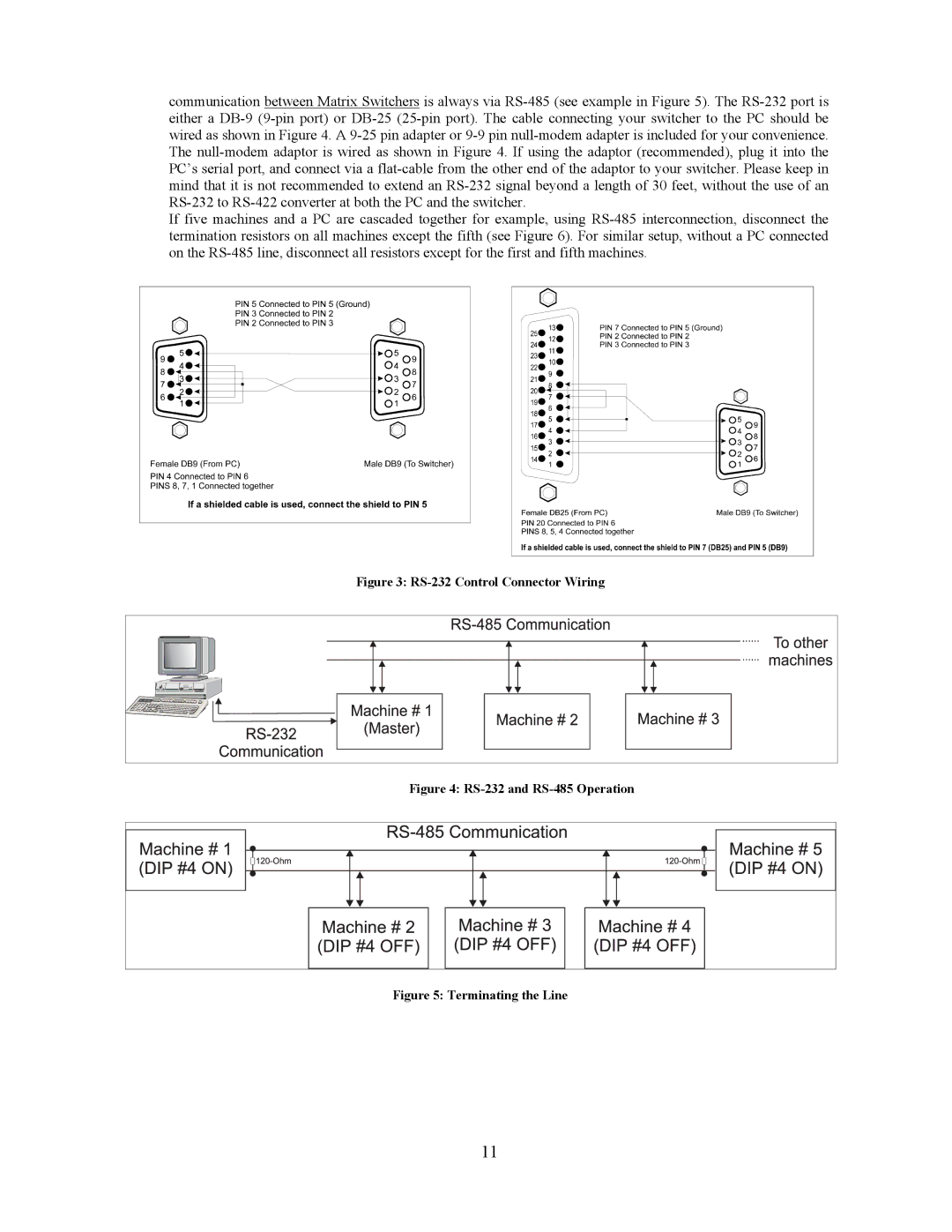
Figure 3: RS-232 Control Connector Wiring
Figure 4: RS-232 and RS-485 Operation
Figure 5: Terminating the Line
11