3 Installation
Before beginning, please carefully note:
CAUTION: STATIC ELECTRICITY MAY DAMAGE THE
NOTE — Amplifier Compatibility
The version of the
Should you later wish to change the amplifier you are using for your
3.1Prepare the IQ–P.I.P.–DSP
1.Set the IQ address switch SW1. By giving each IQ component a unique address, it can be individu- ally controlled and monitored. Whenever the IQ System wants to send a command to just one IQ component, it first sends its address and then the
SW1
|
|
|
|
|
|
|
|
|
|
|
|
|
|
|
|
|
|
|
|
|
|
| OUT |
| |
|
|
|
|
|
|
|
|
|
|
|
|
|
|
|
| IN |
| CROWN |
|
|
| ||||
|
|
|
|
|
|
|
|
|
|
|
|
|
|
|
|
|
| BUS |
|
|
|
| |||
|
|
|
|
|
|
|
|
|
|
|
|
|
|
|
|
|
|
|
|
|
|
| |||
|
|
|
|
|
|
|
|
|
|
|
| DSPI |
|
|
|
|
|
|
|
|
|
|
|
| |
|
|
|
|
|
|
|
|
|
|
|
| DIO | OU | T |
|
|
|
|
|
|
|
|
|
|
|
|
|
|
|
|
|
|
|
|
|
| AU |
|
|
|
|
|
|
|
| RING = |
| ||||
|
|
|
|
|
|
|
|
|
|
|
|
|
|
|
|
| ### | ||||||||
|
|
|
|
|
| PUSH |
|
|
|
|
|
|
|
|
|
| |||||||||
|
|
| .P |
|
|
|
|
|
|
|
|
|
|
|
|
|
| T | . | ||||||
|
|
|
|
|
|
|
|
|
|
|
| = |
|
|
| ER |
| PU | DSP# | ||||||
|
|
|
|
|
|
|
|
|
|
|
|
|
|
|
|
| W |
|
|
| |||||
|
|
|
|
|
|
|
|
|
|
|
|
|
|
|
|
|
|
| A |
|
| ||||
| . | I | . |
|
|
|
|
|
|
|
|
| TIP |
| PO |
| IN |
|
| ||||||
|
|
| PUSH |
|
|
|
|
|
| CH |
| T. |
| 40 | 0 m |
|
|
| |||||||
| P |
|
|
|
|
|
|
|
|
| EX |
| VD | C / |
|
|
|
| |||||||
|
|
|
|
|
|
|
|
|
|
|
|
|
|
| 24 |
|
|
|
|
| |||||
|
|
|
|
|
|
|
|
|
| CH |
|
|
|
|
|
|
|
|
|
|
|
| |||
|
|
|
|
|
|
|
|
|
|
|
|
|
|
|
|
|
|
|
|
|
|
|
| ||
|
|
|
|
|
|
|
|
|
|
|
|
|
|
|
|
|
|
|
|
|
|
|
|
| |
|
|
|
|
|
|
|
| IN | C H | - 1 |
|
|
|
|
|
|
|
|
|
|
|
|
|
|
|
|
|
|
|
|
|
|
|
|
|
|
|
|
|
|
|
|
|
|
|
|
|
|
| ||
|
|
|
|
|
|
| AUDIO |
|
|
|
|
|
|
|
|
|
|
|
|
|
|
|
|
| |
2 | 1 |
|
| C H - | 2 |
|
|
|
|
|
|
|
|
|
|
|
|
|
|
|
|
|
| ||
D |
|
|
|
|
|
|
|
|
|
|
|
|
|
|
|
|
|
|
|
| |||||
|
|
|
|
|
|
|
|
|
|
|
|
|
|
|
|
|
|
|
|
|
| ||||
3 | GN |
|
|
|
|
|
|
|
|
|
|
|
|
|
|
|
|
|
|
|
|
|
|
| |
Fig. 3.1 IQ Address Switch (SW1) Location
command down the Crown Bus.
The
is used to set the IQ address of the
Different IQ components in the same Crown Bus loop can have the same address. For example, both an
A valid IQ address is any number from 1 to 250. Do not use a number higher than 250 since they are reserved for special use. An address of “0” (zero) should never be used except to put the
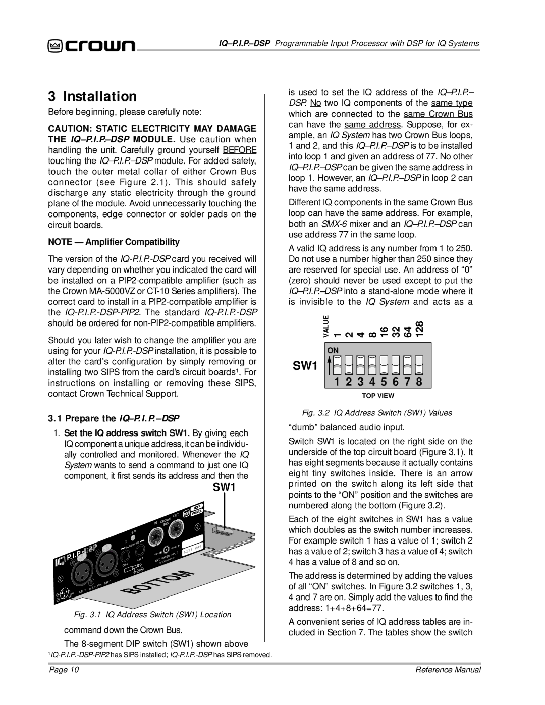
VALUE1248163264128
ON
SW1
1 2 3 4 5 6 7 8
TOP VIEW
Fig. 3.2 IQ Address Switch (SW1) Values
“dumb” balanced audio input.
Switch SW1 is located on the right side on the underside of the top circuit board (Figure 3.1). It has eight segments because it actually contains eight tiny switches inside. There is an arrow printed on the switch along its left side that points to the “ON” position and the switches are numbered along the bottom (Figure 3.2).
Each of the eight switches in SW1 has a value which doubles as the switch number increases. For example switch 1 has a value of 1; switch 2 has a value of 2; switch 3 has a value of 4; switch 4 has a value of 8 and so on.
The address is determined by adding the values of all “ON” switches. In Figure 3.2 switches 1, 3, 4 and 7 are on. Simply add the values to find the address: 1+4+8+64=77.
A convenient series of IQ address tables are in- cluded in Section 7. The tables show the switch
Page 10 | Reference Manual |