than 1,000 feet (305
•Never use the ground wire in a mic snake line. It may sometimes be convenient to run Crown Bus data signals to and from stage monitor amplifiers along unused wire pairs in a mic snake. If this is done, do not use the ground wire which is nor- mally connected to pin 1 on an XLR connector or data noise will be added to the audio lines. Use only the signal lines which normally connect to pins 2 and 3 of the XLRs. The maximum possible Crown Bus loop distance will be less because typical mic cables have high capacitance.
Outside RF interference is seldom a problem for a Crown Bus
There are two different types of connectors used for Crown Bus wiring: DIN connectors and screw terminal plugs. The
| IQ Component Input | |||||||
4 | 1 | 5 |
|
| 1 | |||
|
|
|
| |||||
3 | 2 | 4 |
|
| 2 | |||
|
|
| 3 | |||||
|
|
|
|
|
|
| ||
GND 1 |
|
|
| 1 | Input | |||
|
|
| ||||||
Output (+) | 2 |
|
|
| 2 | Input (+) | ||
|
| |||||||
Not used 3 | Optional Shield | 3 | GND | |||||
Not used 4 | 4 | Not used | ||||||
| ||||||||
|
|
|
|
| 5 | Not used | ||
Figure 3.7 IQ–P.I.P.–DSP Output Connection to Another IQ Component with DIN Connectors
The next two figures show how to connect the IQ–
should be connected to an IQ component with a screw terminal plug.
IQ Mixer | |||
|
| OUT | IN |
4 | 1 | + – + | – |
3 | 2 |
|
|
GND 1 | Output (+) | ||
Output (+) | 2 | Output | |
Not used 3 | Input (+) | ||
Not used 4 | Input | ||
Figure 3.8 IQ–P.I.P.–DSP Output Connection to an IQ Component with a Screw Terminal Plug Connector
IQ Mixer | |||
OUT | IN | 5 | 1 |
+ – + | – | ||
|
| 4 | 2 |
|
|
| 3 |
Output (+) |
| 1 | Input |
Output |
| 2 | Input (+) |
Input (+) |
| 3 | GND |
Input |
| Optional Shield | Not used |
| 4 | ||
|
| 5 | Not used |
Figure 3.9 An IQ Component with Screw Terminal
Plug Connected to the IQ–P.I.P.–DSP Input
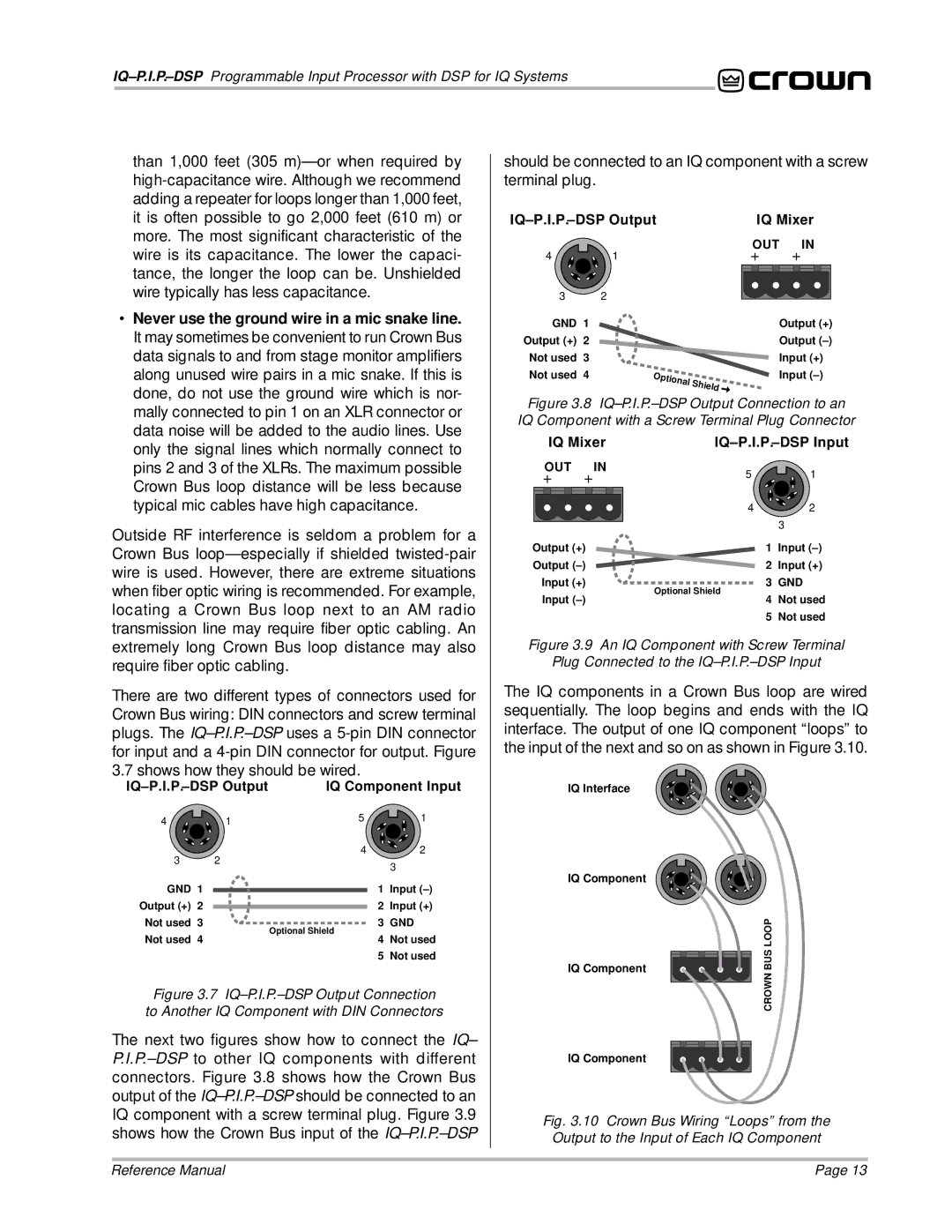
The IQ components in a Crown Bus loop are wired sequentially. The loop begins and ends with the IQ interface. The output of one IQ component “loops” to the input of the next and so on as shown in Figure 3.10.
IQ Interface
IQ Component |
| |
IQ Component | BUS LOOP | |
CROWN | ||
| ||
IQ Component |
|
Fig. 3.10 Crown Bus Wiring “Loops” from the Output to the Input of Each IQ Component
Reference Manual | Page 13 |