Section 3.8 for more information.
3.5 Adjust the Levels & Scale Factors
13.Turn the level controls of the amplifier to their full or maximum setting. This is required by the IQ–P.I.P.–DSP. If needed, use the software-con- trolled input attenuators on the IQ–P.I.P.–DSPto re- duce the audio levels.
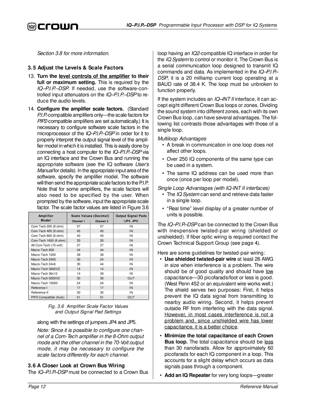
14.Configure the amplifier scale factors. (Standard P.I.P.-compatible amplifiers only—the scale factors for PIP2-compatible amplifiers are set automatically.) It is necessary to configure software scale factors in the microprocessor of the IQ–P.I.P.–DSPin order for it to properly interpret the output signal level of the ampli- fier model in which it is installed. This is easily done by connecting a host computer to the IQ–P.I.P.–DSPvia an IQ interface and the Crown Bus and running the appropriate software (see the IQ software User’s Manual for details). In the appropriate input area of the software, specify the amplifier model. The software will then send the appropriate scale factors to the P.I.P. Note that for some amplifiers, the scale factors will also need to be specified by the user. When prompted by the software, input the appropriate scale factor. The scale factor values are listed in Figure 3.6
Amplifier | Scale Values (Decimal) | Output Signal Pads |
Model | Channel 1 | | Channel 2 | (JP4, JP5) |
|
Com-Tech 200 (8 ohm) | 57 | | 57 | IN |
Com-Tech 400 (8 ohm) | 45 | | 45 | IN |
Com-Tech 800 (8 ohm) | 40 | | 40 | IN |
| | | | |
Com-Tech 1600 (8 ohm) | 30 | | 30 | IN |
All Com-Tech (70-volt) | 27 | | 27 | IN |
Macro-Tech 600 | 44 | | 44 | IN |
Macro-Tech 1200 | 39 | | 39 | IN |
| | | | |
Macro-Tech 2400 | 30 | | 24 | IN |
Macro-Tech 24x6 | 30 | | 44 | IN |
Macro-Tech 3600VZ | 14 | | 14 | IN |
Macro-Tech 36x12 | 14 | | 39 | IN |
| | | | |
Macro-Tech 5000VZ | 30 | | 30 | OUT |
Macro-Tech 10000 | 24 | | 24 | IN |
Reference I | 17 | | 17 | IN |
Reference II | 30 | | 30 | IN |
| | | | |
PIP2-Compatible (Auto) | 51 | | 51 | OUT |
Fig. 3.6 Amplifier Scale Factor Values
and Output Signal Pad Settings
along with the settings of jumpers JP4 and JP5.
Note: Since it is possible to configure one chan- nel of a Com-Tech amplifier in the 8-Ohm output mode and the other channel in the 70-Volt output mode, it may be necessary to configure the scale factors differently for each channel.
3.6 A Closer Look at Crown Bus Wiring
The IQ–P.I.P.–DSPmust be connected to a Crown Bus
loop having an IQ2-compatible IQ interface in order for the IQ System to control or monitor it. The Crown Bus is a serial communication loop designed to transmit IQ commands and data. As implemented in the IQ–P.I.P.– DSP, it is a 20 milliamp current loop operating at a BAUD rate of 38.4 K. The loop must be unbroken to function properly.
If the system includes an IQ–INT II interface, it can ac- cept eight different Crown Bus loops or zones. Dividing the sound system into different zones, each with its own Crown Bus loop, can have several advantages. The fol- lowing list contrasts those advantages with those of a single loop.
Multiloop Advantages
•A break in communication in one loop does not affect other loops.
•Over 250 IQ components of the same type can be used in a system.
•The same IQ address can be used more than once (once per loop per model).
Single Loop Advantages (with IQ-INT II interfaces)
•The IQ System can send and retrieve data faster in a single loop.
•“Real time” level display of a greater number of units is possible.
The IQ–P.I.P.–DSPcan be connected to the Crown Bus with inexpensive twisted-pair wiring (shielded or unshielded). If fiber optic wiring is required contact the Crown Technical Support Group (see page 4).
Here are some guidelines for twisted-pair wiring:
•Use shielded twisted-pair wire at least 26 AWG in size when interference is a problem. The wire should be of good quality and should have lowcapacitance—30 picofarads/foot or less is good. (West Penn 452 or an equivalent wire works well.) The shield serves two purposes: First, it helps prevent the IQ data signal from transmitting to nearby audio wiring. Second, it helps prevent outside RF from interfering with the data signal. However, in most cases interference is not a problem and, since unshielded wire has lower capacitance, it is a better choice.
•Minimize the total capacitance of each Crown Bus loop. The total capacitance should be less than 30 nanofarads. Allow for approximately 60 picofarads for each IQ component in a loop. This accounts for a slight delay which occurs as data signals pass through a component.
•Add an IQ Repeater for very long loops—greater