settings for all 250 addresses.
2.Set the jumpers JP4 and JP5. If the
3.2 Prepare the Amplifier
3.Turn down the level controls (full counter- clockwise) and turn off the amplifier.
4.Disconnect the amplifier’s power cord.
5.Remove the existing P.I.P. or cover panel from the amplifier back panel (two screws). For PIP2 amplifi- ers this may involve disconnecting the P.I.P. from a PIP2 input adapter (Figure 3.4). If a PIP2 input adapter is already present, do not remove the rib- bon cables from the adapter. Otherwise you will have to reconnect them in Step 9.
6.Set the amplifier input sensitivity to 0.775 V. (See the amplifier’s Reference Manual.)
3.3Install the IQ–P.I.P.–DSP into the Amplifier
7.Carefully ground yourself to the chassis of the amplifier before installing the
8.Install the IQ–P.I.P.–DSP into the amplifier:
Standard P.I.P. Amplifiers: Align the edges of the
PIP2 Amplifiers: Connect the PIP2 input adapter to the two input cables of the amplifier (Figure
BACK | PANEL |
OF AMPLIFIER | |
|
| . |
| P | |
.I. |
| |
P |
|
|
MODULE | ||
Fig. 3.3 Installation into a Standard P.I.P. Amplifier
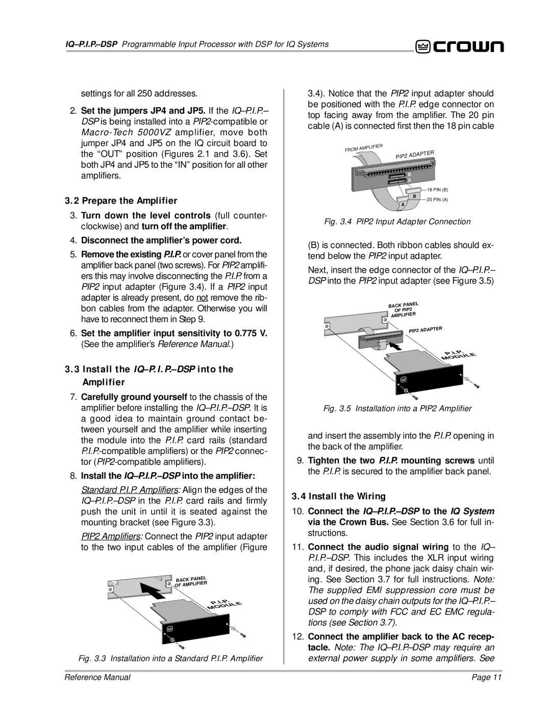
3.4). Notice that the PIP2 input adapter should be positioned with the P.I.P. edge connector on top facing away from the amplifier. The 20 pin cable (A) is connected first then the 18 pin cable
FROM | AMPLIFIER |
|
PIP2 | ADAPTER |
| B |
| A |
| 18 PIN (B) |
| B |
A | 20 PIN (A) |
|
Fig. 3.4 PIP2 Input Adapter Connection
(B)is connected. Both ribbon cables should ex- tend below the PIP2 input adapter.
Next, insert the edge connector of the
BACK | PANEL |
|
OF PIP2 |
| |
AMPLIFIER |
| |
| PIP2 | ADAPTER |
|
| . | |
.I.P |
| ||
P |
|
| LE |
|
| U | |
| D |
| |
O |
|
| |
M |
|
|
|
Fig. 3.5 Installation into a PIP2 Amplifier
and insert the assembly into the P.I.P. opening in the back of the amplifier.
9.Tighten the two P.I.P. mounting screws until the P.I.P. is secured to the amplifier back panel.
3.4 Install the Wiring
10.Connect the
11.Connect the audio signal wiring to the IQ–
12.Connect the amplifier back to the AC recep- tacle. Note: The
external power supply in some amplifiers. See
Reference Manual | Page 11 |