5 Technical Information
The purpose of the
5.1 Audio Signals
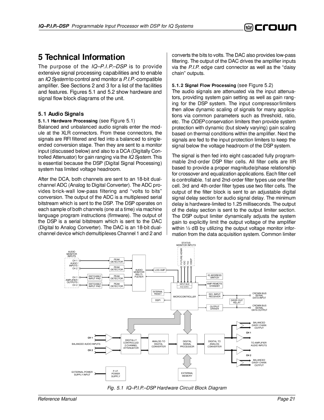
5.1.1 Hardware Processing (see Figure 5.1)
Balanced and unbalanced audio signals enter the mod- ule at the XLR connectors. From these connectors, the signals are RFI filtered and fed into a balanced to single- ended conversion stage. Then they are sent to a monitor input (discussed below) and also to a DCA (Digitally Con- trolled Attenuator) for gain ranging via the IQ System. This is essential because the DSP (Digital Signal Processing) system has limited voltage headroom.
After the DCA, both channels are sent to an
converts the bits to volts. The DAC also provides
5.1.2 Signal Flow Processing (see Figure 5.2)
The audio signals are attenuated via the input attenua- tors, providing system gain setting as well as gain rang- ing for the DSP system. The input compressor/limiters then allow dynamic scaling of signals for many applica- tions via common parameters such as threshold, ratio, etc. The ODEP conservation limiters then provide system protection with dynamic (but slowly varying) gain scaling based on thermal conditions within the amplifier. Next the signals are fed to the input protection limiters to keep the signal below the voltage headroom of the DSP system.
The signal is then fed into eight cascaded fully program- mable
STATUS
MONITOR INPUTS
AUDIO
MONITOR
INPUTS
CH 1
AUDIO
INPUTS
CH 2
CH 1
AMPLIFIER OUTPUTS
CH 2
SWITCHABLE INPUT PAD
SWITCHABLE INPUT PAD
PEAK
DETECTOR
PEAK |
|
|
|
|
|
|
|
DETECTOR |
| AUDIO |
|
| LOG AMP | ||
|
| MONITOR |
|
|
|
| |
PEAK |
| MULTI- |
|
|
|
| |
| PLEXER |
|
|
|
| ||
DETECTOR |
|
|
|
|
|
|
|
PEAK |
|
|
|
|
|
|
|
DETECTOR |
|
|
|
|
|
|
|
|
|
|
|
|
| ||
|
|
|
| EXTERNAL |
|
| |
|
|
|
|
| RESET |
|
|
FUTURE HDWR IOC Vcc | ODEP |
|
| |
|
| IQ ADDRESS |
| |
|
| SWITCH |
| |
INPUT MUX |
| AMP REMOTE |
| |
A/D CONV. |
| STANDBY |
| |
|
| ISO. INPUT | CROWN BUS | |
|
| SERIAL | ||
MICROCONTROLLER | RECEIVER | |||
DATA INPUT | ||||
|
|
| ||
DSPI
RELAY |
CH 1
DIGITALLY
ANALOG TO
OUTPUT
DRIVER
DIGITAL | DIGITAL TO |
CROWN BUS
SERIAL
DATA OUTPUT
BALANCED
OUTPUT
CH 1
CONTROLLED
BALANCED AUDIO INPUTSDIGITAL
SIGNAL | ANALOG |
TO AMPLIFIER AUDIO INPUTS
ATTENUATOR
CH 2 |
|
|
|
|
| P.I.P. | |
EXTERNAL POWER |
|
| |
| POWER | ||
SUPPLY INPUT |
| ||
| SUPPLY | ||
|
| ||
CONVERTER
PROCESSOR | CONVERTER |
EXTERNAL
MEMORY
CH 2
![]() BALANCED
BALANCED
OUTPUT
Fig. 5.1 IQ–P.I.P.–DSP Hardware Circuit Block Diagram
Reference Manual | Page 21 |