D E


P.I.P.-DSP
PUSHPUSH
Front View
DSPI | I N CROWN OUT |
| BUS |
AUDIO OUT |
|
21
3
GND
C H - 2 AUDIO IN C H - 1
CH |
| TIP = | RING = |
|
|
| ||
|
|
|
| |||||
|
|
|
|
|
| |||
|
|
| EXT. POWER INPUT |
| DSP#.### |
| ||
|
|
|
| 24 VDC / 400 mA |
|
| ||
|
|
|
|
|
|
|
|
|
|
|
|
|
|
|
|
|
|
A | B | B | C | C |
|
| F G H | A | |||||||||||||
|
|
|
|
|
|
|
|
|
|
|
|
|
|
|
|
|
|
|
|
|
|
|
|
|
|
|
|
|
|
|
|
|
|
|
|
|
|
|
|
|
|
|
|
|
|
|
|
|
|
|
|
|
|
|
|
|
|
|
|
|
|
|
|
|
|
Bottom View | AVOID STATIC DAMAGE! | |
GROUND YOURSELF TO THE OUTER | ||
| ||
| METAL COLLAR OF ONE OF THE | |
| CROWN BUS CONNECTORS. | |
| K | |
| RN1 |
SW1
N
JP4
CH1
I
J
JP5RN2 CH2
J K
M
L
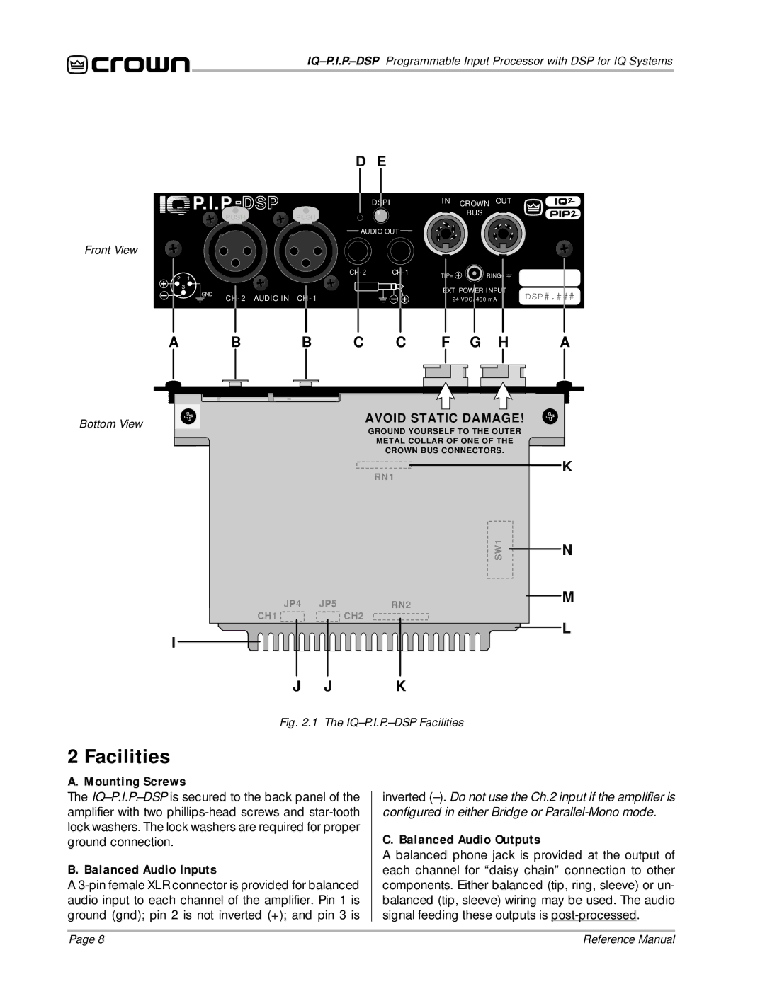
Fig. 2.1 The IQ–P.I.P.–DSP Facilities
2 Facilities
A. Mounting Screws
The
B. Balanced Audio Inputs
A
inverted
C. Balanced Audio Outputs
A balanced phone jack is provided at the output of each channel for “daisy chain” connection to other components. Either balanced (tip, ring, sleeve) or un- balanced (tip, sleeve) wiring may be used. The audio signal feeding these outputs is
Page 8 | Reference Manual |