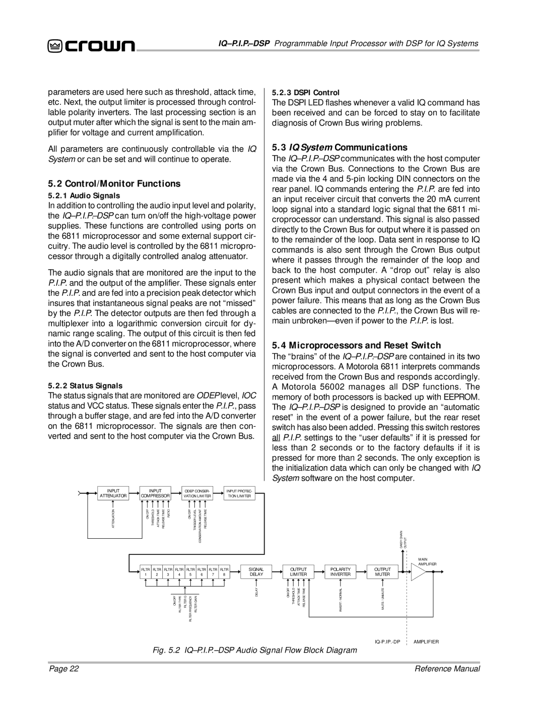
parameters are used here such as threshold, attack time, etc. Next, the output limiter is processed through control- lable polarity inverters. The last processing section is an output muter after which the signal is sent to the main am- plifier for voltage and current amplification.
All parameters are continuously controllable via the IQ System or can be set and will continue to operate.
5.2 Control/Monitor Functions
5.2.1 Audio Signals
In addition to controlling the audio input level and polarity, the
The audio signals that are monitored are the input to the P.I.P. and the output of the amplifier. These signals enter the P.I.P. and are fed into a precision peak detector which insures that instantaneous signal peaks are not “missed” by the P.I.P. The detector outputs are then fed through a multiplexer into a logarithmic conversion circuit for dy- namic range scaling. The output of this circuit is then fed into the A/D converter on the 6811 microprocessor, where the signal is converted and sent to the host computer via the Crown Bus.
5.2.2 Status Signals
The status signals that are monitored are ODEP level, IOC status and VCC status. These signals enter the P.I.P., pass through a buffer stage, and are fed into the A/D converter on the 6811 microprocessor. The signals are then con- verted and sent to the host computer via the Crown Bus.
5.2.3 DSPI Control
The DSPI LED flashes whenever a valid IQ command has been received and can be forced to stay on to facilitate diagnosis of Crown Bus wiring problems.
5.3 IQ System Communications
The
5.4 Microprocessors and Reset Switch
The “brains” of the
INPUT | INPUT |
|
|
| ODEP CONSER- | INPUT PROTEC- | |||||
ATTENUATOR | COMPRESSOR |
|
| VATION LIMITER | TION LIMITER | ||||||
ATTENUATION | ON/OFF | THRESHOLD ATTACK TIME | RELEASE TIME RATIO |
|
|
| ON/OFF TRIGGER LEVEL | CONSERVATION AMOUNT RELEASE TIME |
|
|
|
| FLTR | FLTR | FLTR | FLTR |
| FLTR | FLTR | FLTR | FLTR | SIGNAL | |
| 1 | 2 | 3 |
| 4 |
| 5 | 6 | 7 | 8 | DELAY |
|
|
|
| ON/OFF | FILTER TYPE | FILTER Q | FREQUENCY FILTER GAIN |
|
|
| DELAY |
|
|
|
|
|
|
| FILTER |
|
|
|
|
DAISY CHAIN | OUTPUT |
MAIN
AMPLIFIER
| OUTPUT | POLARITY |
| OUTPUT | ||||
ON/OFF | LIMITER | INVERTER |
| MUTER | ||||
|
|
|
|
|
|
| ||
|
|
|
|
|
|
|
| |
THRESHOLD ATTACK TIME RELEASE TIME | INVERT / NORMAL |
| MUTE / UNMUTE | |||||
Fig. 5.2 IQ–P.I.P.–DSP Audio Signal Flow Block Diagram
Page 22 | Reference Manual |