Watchdog
WDF
CY14B101K
Figure 5. Interrupt Block Diagram
Timer
Power
Monitor
VINT
Clock Alarm
WIE
PF
PFE
AF
AIE
| P/L | VCC | |||
|
|
|
|
|
|
|
|
|
|
|
|
|
|
|
|
|
|
|
|
|
|
|
|
Pin ![]()
![]() Driver
Driver ![]()
![]()
H/L VSS
| WDF - Watchdog Timer Flag |
| WIE - Watchdog Interrupt |
| Enable |
| PF - Power Fail Flag |
INT | PFE - Power Fail Enable |
| AF - Alarm Flag |
| AIE - Alarm Interrupt Enable |
| P/L - Pulse Level |
| H/L - High/Low |
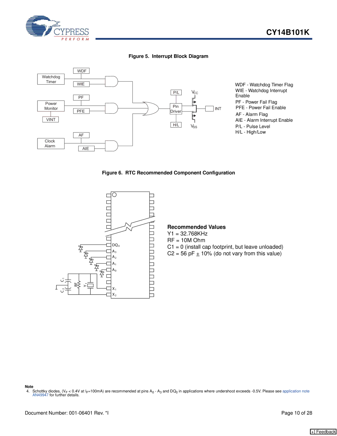
Figure 6. RTC Recommended Component Configuration
1 |
|
C | Y |
RF | |
| 1 |
2 |
|
C |
|
![]() DQ 0
DQ 0
![]()
![]() A3
A3
![]()
![]() A2
A2 ![]()
![]()
![]()
![]() A1
A1
![]()
![]()
![]()
![]() A0
A0
![]()
![]() X1
X1
![]() X2
X2
Recommended Values
Y1 = 32.768KHz
RF = 10M Ohm
C1 = 0 (install cap footprint, but leave unloaded) C2 = 56 pF + 10% (do not vary from this value)
Note
4.Schottky diodes, (VF < 0.4V at IF=100mA) are recommended at pins A0 - A3 and DQ0 in applications where undershoot exceeds
Document Number: | Page 10 of 28 |
[+] Feedback