CY7C0850AV, CY7C0851AV
CY7C0852AV, CY7C0853AV
Switching Waveforms (continued)
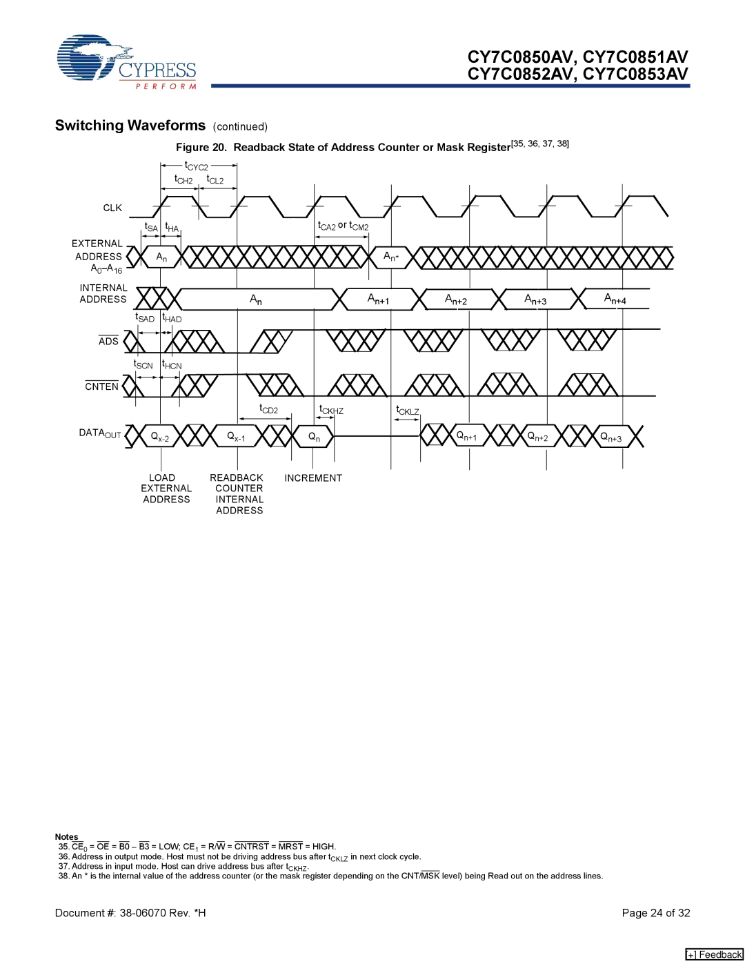
Figure 20. Readback State of Address Counter or Mask Register[35, 36, 37, 38]
CLK
EXTERNAL
ADDRESS
| tCYC2 | |
| tCH2 | tCL2 |
tSA | tHA |
|
An |
| |
tCA2 or tCM2 |
An* |
INTERNAL ADDRESS
AnAn+1
tSAD tHAD
ADS |
tSCN tHCN
CNTEN ![]()
tCD2 | tCKHZ | tCKLZ | ||||
|
|
|
|
|
|
|
DATAOUT | Q | Q | Q | Qn+1 | Q | n+2 | Q | ||
|
|
| n |
|
| n+3 |
LOAD READBACK INCREMENT
EXTERNAL COUNTER
ADDRESS INTERNAL
ADDRESS
Notes
35.CE0 = OE = B0 – B3 = LOW; CE1 = R/W = CNTRST = MRST = HIGH.
36.Address in output mode. Host must not be driving address bus after tCKLZ in next clock cycle.
37.Address in input mode. Host can drive address bus after tCKHZ.
38.An * is the internal value of the address counter (or the mask register depending on the CNT/MSK level) being Read out on the address lines.
Document #: | Page 24 of 32 |
[+] Feedback