| CY7C1310AV18 |
PRELIMINARY | CY7C1312AV18 |
CY7C1314AV18 | |
|
|
TAP AC Switching Characteristics Over the Operating Range[26, 27]
Parameter | Description | Min. | Max. | Unit |
tTCYC | TCK Clock Cycle Time | 100 |
| ns |
tTF | TCK Clock Frequency |
| 10 | MHz |
tTH | TCK Clock HIGH | 40 |
| ns |
tTL | TCK Clock LOW | 40 |
| ns |
|
|
|
| |
|
|
|
|
|
tTMSS | TMS | 10 |
| ns |
tTDIS | TDI | 10 |
| ns |
tCS | Capture | 10 |
| ns |
Hold Times |
|
|
|
|
tTMSH | TMS Hold after TCK Clock Rise | 10 |
| ns |
tTDIH | TDI Hold after Clock Rise | 10 |
| ns |
tCH | Capture Hold after Clock Rise | 10 |
| ns |
Output Times |
|
|
|
|
|
|
|
|
|
tTDOV | TCK Clock LOW to TDO Valid |
| 20 | ns |
tTDOX | TCK Clock LOW to TDO Invalid | 0 |
| ns |
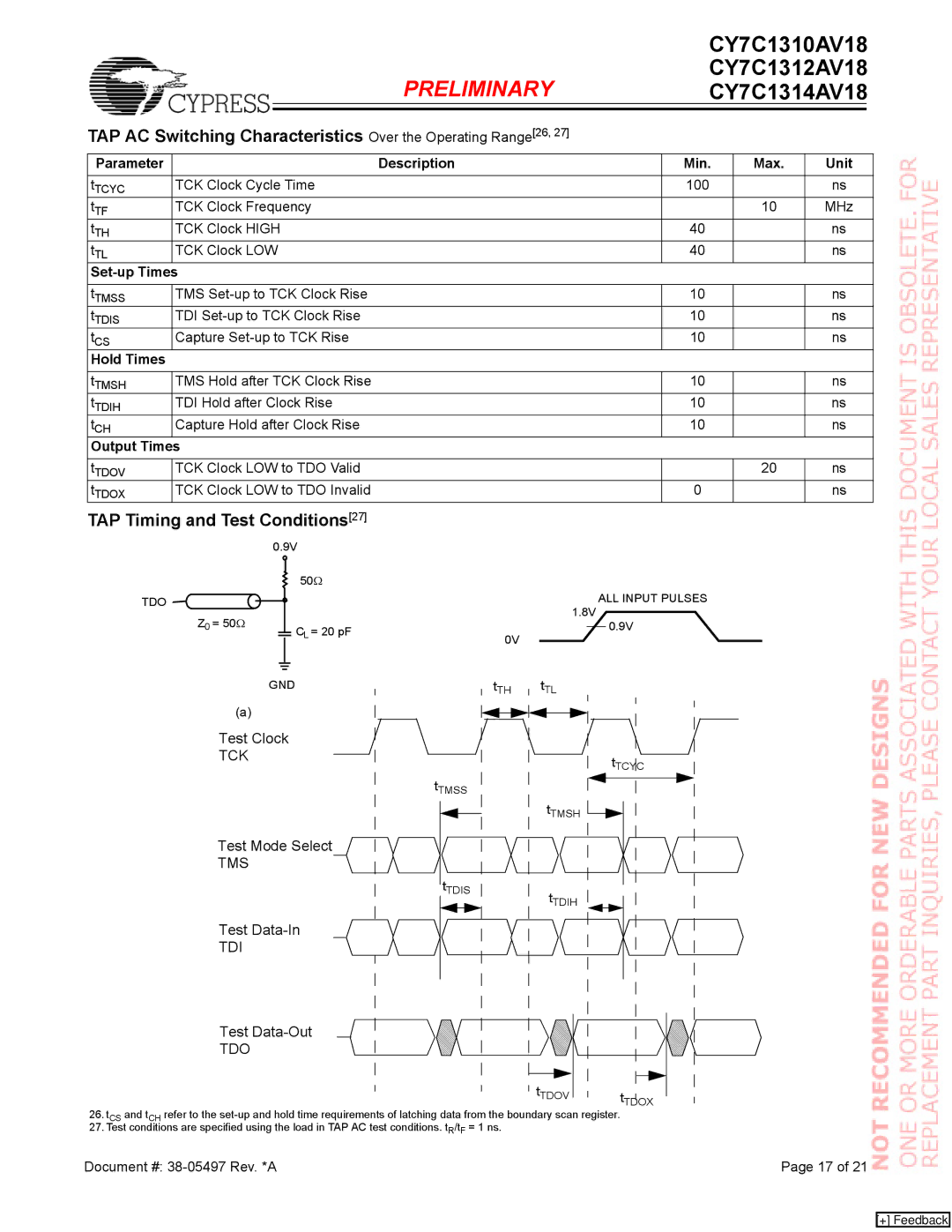
TAP Timing and Test Conditions[27]
|
|
| 0.9V |
|
|
|
| |||||||
|
|
|
|
|
|
|
|
|
| 50Ω |
|
|
|
|
|
|
|
|
|
|
|
|
|
|
|
|
|
| |
|
|
|
|
|
|
|
|
|
|
|
|
|
| |
TDO |
|
|
|
|
|
|
|
|
|
|
|
|
|
|
Z0 | = 50Ω |
|
|
|
|
|
|
| CL = 20 pF |
|
|
| 0V | |
|
|
|
|
|
|
|
|
|
| |||||
|
|
|
|
|
|
|
|
|
|
| ||||
|
|
|
|
|
|
|
|
|
|
|
|
| ||
|
|
|
|
|
|
|
|
|
|
|
|
|
| |
|
|
|
|
|
|
|
|
|
|
|
|
| ||
|
|
|
|
|
|
|
|
|
|
| ||||
|
|
| GND |
|
|
| tTH | |||||||
|
|
|
|
| ||||||||||
(a)
ALL INPUT PULSES
1.8V
0.9V
tTL
Test Clock
TCK
Test Mode Select
TMS
Test
TDI
Test
TDO
tTMSS
tTDIS
tTMSH
tTDIH
tTDOV
tTCYC
tTDOX
26.tCS and tCH refer to the
27.Test conditions are specified using the load in TAP AC test conditions. tR/tF = 1 ns.
Document #: | Page 17 of 21 |
[+] Feedback