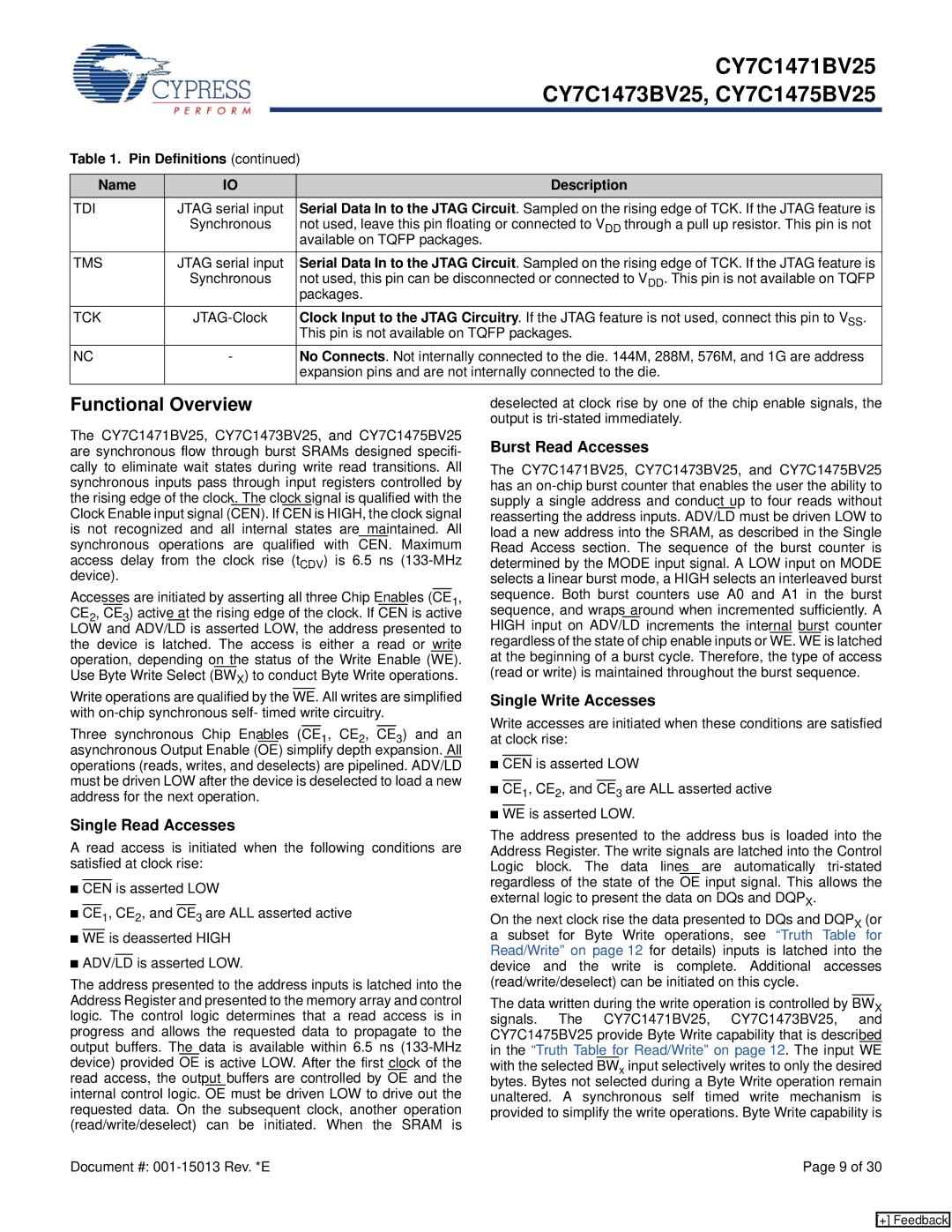
Cypress CY7C1471BV25 manual Functional Overview, Pin Definitions, Name Description, Tdi, Tms

Models: CY7C1475BV25 CY7C1473BV25 CY7C1471BV25

1 30
Download 30 pages 32.83 Kb
Page 9
Image 9


CY7C1471BV25


CY7C1473BV25, CY7C1475BV25


Table 1. Pin Definitions (continued)


Name

IO

Description

TDI

JTAG serial input

Serial Data In to the JTAG Circuit. Sampled on the rising edge of TCK. If the JTAG feature is


Synchronous

not used, leave this pin floating or connected to VDD through a pull up resistor. This pin is not


available on TQFP packages.

TMS

JTAG serial input

Serial Data In to the JTAG Circuit. Sampled on the rising edge of TCK. If the JTAG feature is


Synchronous

not used, this pin can be disconnected or connected to VDD. This pin is not available on TQFP


packages.

TCK

JTAG-Clock

Clock Input to the JTAG Circuitry. If the JTAG feature is not used, connect this pin to VSS.


This pin is not available on TQFP packages.

NC

-


No Connects. Not internally connected to the die. 144M, 288M, 576M, and 1G are address


expansion pins and are not internally connected to the die.

Functional Overview

The CY7C1471BV25, CY7C1473BV25, and CY7C1475BV25 are synchronous flow through burst SRAMs designed specifi- cally to eliminate wait states during write read transitions. All synchronous inputs pass through input registers controlled by the rising edge of the clock. The clock signal is qualified with the Clock Enable input signal (CEN). If CEN is HIGH, the clock signal is not recognized and all internal states are maintained. All synchronous operations are qualified with CEN. Maximum access delay from the clock rise (tCDV) is 6.5 ns (133-MHz device).

Accesses are initiated by asserting all three Chip Enables (CE1, CE2, CE3) active at the rising edge of the clock. If CEN is active LOW and ADV/LD is asserted LOW, the address presented to the device is latched. The access is either a read or write operation, depending on the status of the Write Enable (WE). Use Byte Write Select (BWX) to conduct Byte Write operations.

Write operations are qualified by the WE. All writes are simplified with on-chip synchronous self- timed write circuitry.

Three synchronous Chip Enables (CE1, CE2, CE3) and an asynchronous Output Enable (OE) simplify depth expansion. All operations (reads, writes, and deselects) are pipelined. ADV/LD must be driven LOW after the device is deselected to load a new address for the next operation.

Single Read Accesses

A read access is initiated when the following conditions are satisfied at clock rise:

CEN is asserted LOW

CE1, CE2, and CE3 are ALL asserted active

WE is deasserted HIGH

ADV/LD is asserted LOW.

The address presented to the address inputs is latched into the Address Register and presented to the memory array and control logic. The control logic determines that a read access is in progress and allows the requested data to propagate to the output buffers. The data is available within 6.5 ns (133-MHz device) provided OE is active LOW. After the first clock of the read access, the output buffers are controlled by OE and the internal control logic. OE must be driven LOW to drive out the requested data. On the subsequent clock, another operation (read/write/deselect) can be initiated. When the SRAM is

deselected at clock rise by one of the chip enable signals, the output is tri-stated immediately.

Burst Read Accesses

The CY7C1471BV25, CY7C1473BV25, and CY7C1475BV25 has an on-chip burst counter that enables the user the ability to supply a single address and conduct up to four reads without reasserting the address inputs. ADV/LD must be driven LOW to load a new address into the SRAM, as described in the Single Read Access section. The sequence of the burst counter is determined by the MODE input signal. A LOW input on MODE selects a linear burst mode, a HIGH selects an interleaved burst sequence. Both burst counters use A0 and A1 in the burst sequence, and wraps around when incremented sufficiently. A HIGH input on ADV/LD increments the internal burst counter regardless of the state of chip enable inputs or WE. WE is latched at the beginning of a burst cycle. Therefore, the type of access (read or write) is maintained throughout the burst sequence.

Single Write Accesses

Write accesses are initiated when these conditions are satisfied at clock rise:

CEN is asserted LOW

CE1, CE2, and CE3 are ALL asserted active

WE is asserted LOW.

The address presented to the address bus is loaded into the Address Register. The write signals are latched into the Control Logic block. The data lines are automatically tri-stated regardless of the state of the OE input signal. This allows the external logic to present the data on DQs and DQPX.

On the next clock rise the data presented to DQs and DQPX (or a subset for Byte Write operations, see “Truth Table for Read/Write” on page 12 for details) inputs is latched into the device and the write is complete. Additional accesses (read/write/deselect) can be initiated on this cycle.

The data written during the write operation is controlled by BWX signals. The CY7C1471BV25, CY7C1473BV25, and CY7C1475BV25 provide Byte Write capability that is described in the “Truth Table for Read/Write” on page 12. The input WE with the selected BWx input selectively writes to only the desired bytes. Bytes not selected during a Byte Write operation remain unaltered. A synchronous self timed write mechanism is provided to simplify the write operations. Byte Write capability is

Document #: 001-15013 Rev. *E

Page 9 of 30

[+] Feedback

Page 9
Image 9
Cypress CY7C1471BV25, CY7C1473BV25, CY7C1475BV25 manual Functional Overview, Pin Definitions, Name Description, Tdi, Tms

CY7C1475BV25, CY7C1473BV25, CY7C1471BV25 specifications

Cypress Semiconductor, a leader in specialized memory solutions, offers a range of high-performance SRAM products, including the CY7C1471BV25, CY7C1473BV25, and CY7C1475BV25. These devices are designed to provide high-speed data processing capabilities along with impressive power efficiency, making them ideal choices for a variety of applications in telecommunications, networking, automotive, and consumer electronics.

The CY7C1471BV25 features a 1-Mbit density, while the CY7C1473BV25 and CY7C1475BV25 support densities of 3-Mbits and 5-Mbits respectively. All three models utilize a 3.3V power supply, and deliver fast access times of 5 ns (for CY7C1471BV25) and 6 ns (for CY7C1473BV25 and CY7C1475BV25). This rapid access enables quicker data retrieval and overall enhanced system performance.

One of the standout features of these SRAM devices is their asynchronous operation, which allows for straightforward integration into existing systems without the need for complex timing protocols. They can be easily interfaced with various microcontrollers and digital signal processors, providing flexibility and ease of use. Additionally, the devices are available in multiple package options, including the widely used TSOP and BGA formats, enabling designers to choose the best fit for their specific layouts.

In terms of technology, these SRAMs leverage advanced CMOS manufacturing processes, which contribute to their low power consumption and high reliability. With sleep modes and low standby current, they are particularly suited for battery-operated devices that demand energy efficiency.

Cypress products are renowned for their reliability and robustness, ensuring that the CY7C1471BV25, CY7C1473BV25, and CY7C1475BV25 can withstand the demands of harsh environments and extended usage. The devices also incorporate features such as high-speed data ports, which facilitate bidirectional data flow, making them optimal for both read and write operations.

In summary, the CY7C1471BV25, CY7C1473BV25, and CY7C1475BV25 SRAMs by Cypress are excellent choices for those seeking high-performance, low-power memory solutions. Their advanced technology, combined with a variety of features and options, caters to the needs of many industries, paving the way for innovative designs in modern electronics.