Table B-3. Parallel Connector Pin Assignments
Pin | Signal | I/O | Definition |
|
|
|
|
|
|
1 | STB# | I/O | Strobe |
|
|
|
|
|
|
2 | PD0 | I/O | Printer data bit 0 |
|
|
|
|
|
|
3 | PD1 | I/O | Printer data bit 1 |
|
|
|
|
|
|
4 | PD2 | I/O | Printer data bit 2 |
|
|
|
|
|
|
5 | PD3 | I/O | Printer data bit 3 |
|
6 | PD4 | I/O | Printer data bit 4 |
|
|
|
|
|
|
7 | PD5 | I/O | Printer data bit 5 |
|
|
|
|
|
|
8 | PD6 | I/O | Printer data bit 6 |
|
|
|
|
|
|
9 | PD7 | I/O | Printer data bit 7 |
|
|
|
|
|
|
10 | ACK# | I | Acknowledge |
|
|
|
|
|
|
11 | BUSY | I | Busy |
|
|
|
|
|
|
12 | PE | I | Paper end |
|
|
|
|
|
|
13 | SLCT | I | Select |
|
14 | AFD# | O | Automatic feed |
|
|
|
|
|
|
15 | ERR# | I | Error |
|
|
|
|
|
|
16 | INIT# | O | Initialize printer |
|
|
|
|
|
|
17 | SLIN# | O | Select in |
|
|
|
|
|
|
| GND | N/A | Ground |
|
|
|
|
|
|
|
|
|
|
|
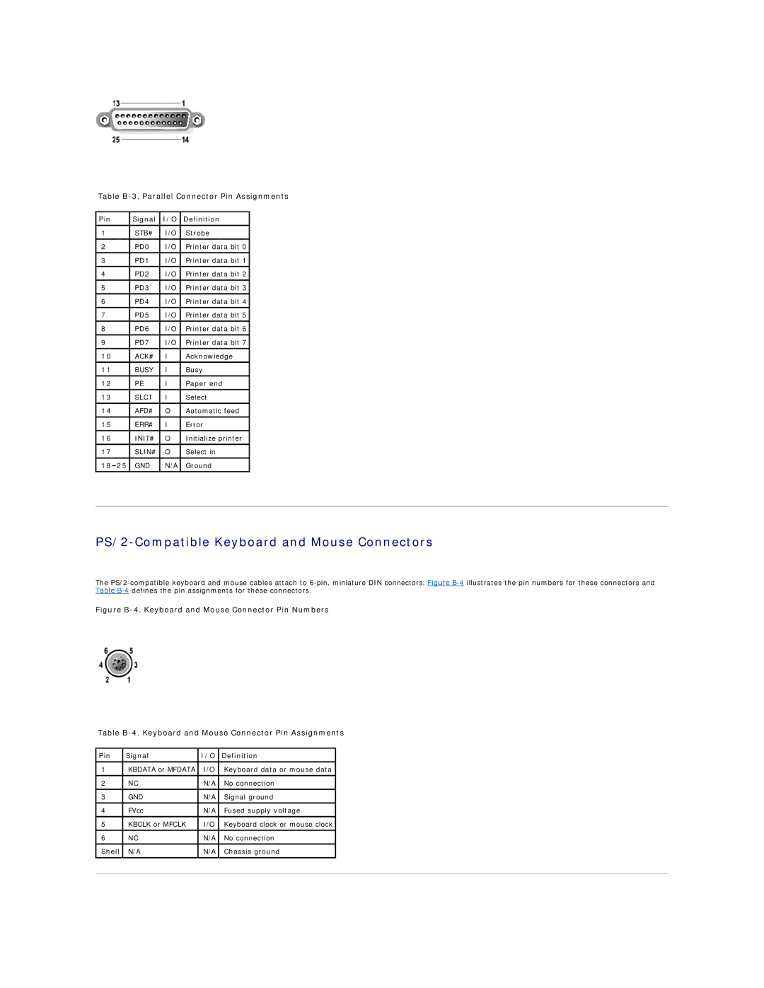
PS/2-Compatible Keyboard and Mouse Connectors
The
Figure B-4. Keyboard and Mouse Connector Pin Numbers
Table B-4. Keyboard and Mouse Connector Pin Assignments
Pin | Signal | I/O | Definition |
|
|
|
|
|
|
1 | KBDATA or MFDATA | I/O | Keyboard data or mouse data |
|
|
|
|
|
|
2 | NC | N/A | No connection |
|
|
|
|
|
|
3 | GND | N/A | Signal ground |
|
|
|
|
|
|
4 | FVcc | N/A | Fused supply voltage |
|
|
|
|
|
|
5 | KBCLK or MFCLK | I/O | Keyboard clock or mouse clock |
|
|
|
|
|
|
6 | NC | N/A | No connection |
|
Shell | N/A | N/A | Chassis ground |
|
|
|
|
|
|
|
|
|
|
|