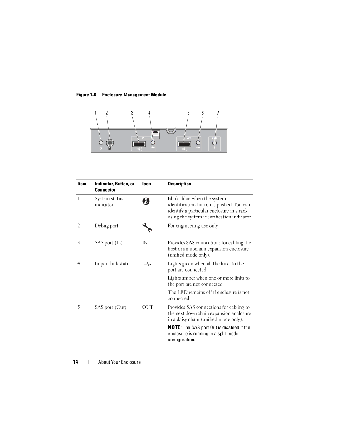
Figure 1-6. Enclosure Management Module
| 1 | 2 | 3 | 4 | 5 | 6 | 7 |
| |
|
|
|
|
|
|
|
|
|
|
|
|
|
|
|
|
|
|
|
|
|
|
|
|
|
|
|
|
|
|
|
|
|
|
|
|
|
|
|
|
|
|
|
|
|
|
|
|
|
|
Item | Indicator, Button, or | Icon | Description |
| Connector |
|
|
|
|
|
|
1 | System status |
| Blinks blue when the system |
| indicator |
| identification button is pushed. You can |
|
|
| identify a particular enclosure in a rack |
|
|
| using the system identification indicator. |
2 | Debug port |
| For engineering use only. |
3 | SAS port (In) | IN | Provides SAS connections for cabling the |
|
|
| host or an upchain expansion enclosure |
|
|
| (unified mode only). |
4 | In port link status |
| Lights green when all the links to the |
|
|
| port are connected. |
|
|
| Lights amber when one or more links to |
|
|
| the port are not connected. |
|
|
| The LED remains off if enclosure is not |
|
|
| connected. |
5 | SAS port (Out) | OUT | Provides SAS connections for cabling to |
|
|
| the next down chain expansion enclosure |
|
|
| in a daisy chain (unified mode only). |
NOTE: The SAS port Out is disabled if the enclosure is running in a
14
About Your Enclosure
