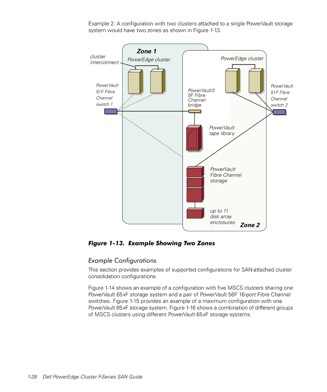
Example 2: A configuration with two clusters attached to a single PowerVault storage system would have two zones as shown in Figure
Zone 1
cluster | PowerEdge cluster | PowerEdge cluster | |
interconnect | |||
|
| ||
PowerVault |
| PowerVault3 | |
51F Fibre |
| ||
Channel |
| 5F Fibre | |
| Channel | ||
switch 1 |
| ||
| bridge |
PowerVault tape library
PowerVault Fibre Channel storage
up to 11 disk array enclosures Zone 2
Figure 1-13. Example Showing Two Zones
PowerVault 51F Fibre Channel switch 2
Example Configurations
This section provides examples of supported configurations for