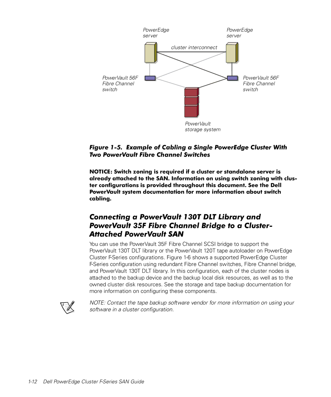
PowerEdge | PowerEdge |
server | server |
PowerVault 56F Fibre Channel switch
cluster interconnect
PowerVault 56F Fibre Channel switch
PowerVault storage system
Figure 1-5. Example of Cabling a Single PowerEdge Cluster With Two PowerVault Fibre Channel Switches
NOTICE: Switch zoning is required if a cluster or standalone server is already attached to the SAN. Information on using switch zoning with clus- ter configurations is provided throughout this document. See the Dell PowerVault system documentation for more information about switch cabling.
Connecting a PowerVault 130T DLT Library and PowerVault 35F Fibre Channel Bridge to a Cluster- Attached PowerVault SAN
You can use the PowerVault 35F Fibre Channel SCSI bridge to support the PowerVault 130T DLT library or the PowerVault 120T tape autoloader on PowerEdge Cluster
NOTE: Contact the tape backup software vendor for more information on using your software in a cluster configuration.