l
| cluster 1 |
|
|
|
| cluster 2 |
| ||||
|
|
|
|
|
|
|
|
|
|
|
|
|
|
|
|
|
|
|
|
|
|
|
|
|
|
|
|
|
|
|
|
|
|
|
|
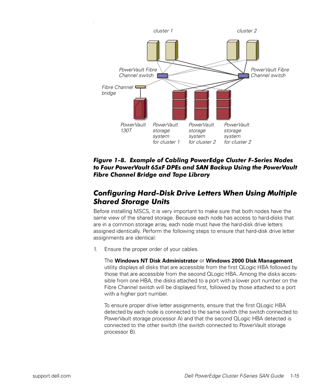
PowerVault Fibre | PowerVault Fibre |
Channel switch | Channel switch |
Fibre Channel ![]()
![]() bridge
bridge
PowerVault | PowerVault | PowerVault | PowerVault |
130T | storage | storage | storage |
| system | system | system |
| for cluster 1 | for cluster 2 | for cluster 2 |
Figure 1-8. Example of Cabling PowerEdge Cluster F-Series Nodes to Four PowerVault 65xF DPEs and SAN Backup Using the PowerVault Fibre Channel Bridge and Tape Library
Configuring
Before installing MSCS, it is very important to make sure that both nodes have the same view of the shared storage. Because each node has access to
1.Ensure the proper order of your cables.
The Windows NT Disk Administrator or Windows 2000 Disk Management utility displays all disks that are accessible from the first QLogic HBA followed by those that are accessible from the second QLogic HBA. Among the disks acces- sible from one HBA, the disks attached to a port with a lower port number on the Fibre Channel switch will be displayed first, followed by those attached to a port with a higher port number.
To ensure proper drive letter assignments, ensure that the first QLogic HBA detected by each node is connected to the same switch (the switch connected to PowerVault storage processor A) and that the second QLogic HBA detected is connected to the other switch (the switch connected to PowerVault storage processor B).
support.dell.com | Dell PowerEdge Cluster |