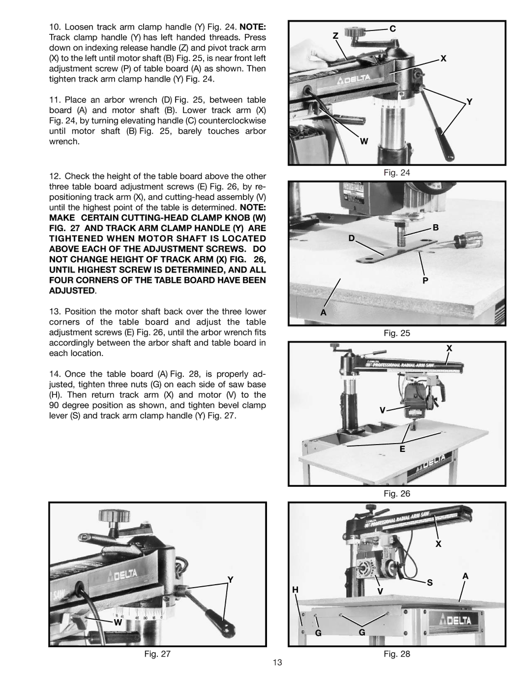
10. Loosen track arm clamp handle (Y) Fig. 24. NOTE: |
Track clamp handle (Y) has left handed threads. Press |
down on indexing release handle (Z) and pivot track arm |
(X) to the left until motor shaft (B) Fig. 25, is near front left |
adjustment screw (P) of table board (A) as shown. Then |
tighten track arm clamp handle (Y) Fig. 24. |
11. Place an arbor wrench (D) Fig. 25, between table |
board (A) and motor shaft (B). Lower track arm (X) |
Fig. 24, by turning elevating handle (C) counterclockwise |
until motor shaft (B) Fig. 25, barely touches arbor |
Z
![]() C
C
X
![]() Y
Y
wrench. |
12. Check the height of the table board above the other |
three table board adjustment screws (E) Fig. 26, by re- |
positioning track arm (X), and |
until the highest point of the table is determined. NOTE: |
MAKE CERTAIN |
FIG. 27 AND TRACK ARM CLAMP HANDLE (Y) ARE |
TIGHTENED WHEN MOTOR SHAFT IS LOCATED |
ABOVE EACH OF THE ADJUSTMENT SCREWS. DO |
NOT CHANGE HEIGHT OF TRACK ARM (X) FIG. 26, |
UNTIL HIGHEST SCREW IS DETERMINED, AND ALL |
FOUR CORNERS OF THE TABLE BOARD HAVE BEEN |
ADJUSTED. |
13. Position the motor shaft back over the three lower |
corners of the table board and adjust the table |
adjustment screws (E) Fig. 26, until the arbor wrench fits |
accordingly between the arbor shaft and table board in |
each location. |
14. Once the table board (A) Fig. 28, is properly ad- |
justed, tighten three nuts (G) on each side of saw base |
(H). Then return track arm (X) and motor (V) to the |
90 degree position as shown, and tighten bevel clamp |
lever (S) and track arm clamp handle (Y) Fig. 27. |
W
Fig. 24
B
D
P
A
Fig. 25
X
V ![]()
E
Fig. 26
Y
![]() W
W
Fig. 27
X
A
S
HV
G G
Fig. 28
13