ASSEMBLING BLADE AND BLADE GUARD TO MACHINE
1.DISCONNECT TOOL FROM POWER SOURCE. USE ONLY 10″ BLADES WITH 5/8″ ARBOR HOLES AND
RATED FOR 5000 RPM OR HIGHER.
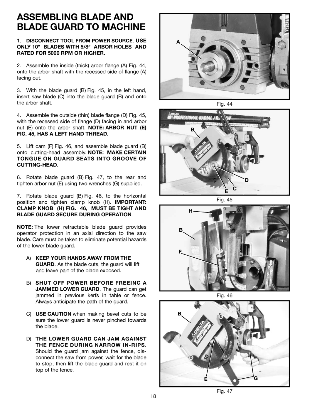
2.Assemble the inside (thick) arbor flange (A) Fig. 44, onto the arbor shaft with the recessed side of flange (A) facing out.
3.With the blade guard (B) Fig. 45, in the left hand, insert saw blade (C) into the blade guard (B) and onto the arbor shaft.
4.Assemble the outside (thin) blade flange (D) Fig. 45, with the recessed side of flange (D) facing in and arbor nut (E) onto the arbor shaft. NOTE: ARBOR NUT (E)
FIG. 45, HAS A LEFT HAND THREAD.
5.Lift cam (F) Fig. 46, and assemble blade guard (B) onto
TONGUE ON GUARD SEATS INTO GROOVE OF CUTTING-HEAD.
6.Rotate blade guard (B) Fig. 47, to the rear and tighten arbor nut (E) using two wrenches (G) supplied.
7.Rotate blade guard (B) Fig. 46, to the horizontal position and tighten clamp knob (H). IMPORTANT:
CLAMP KNOB (H) FIG. 46, MUST BE TIGHT AND BLADE GUARD SECURE DURING OPERATION.
NOTE: The lower retractable blade guard provides operator protection in an axial direction to the saw blade. Care must be taken to eliminate potential hazards of the lower blade guard.
A)KEEP YOUR HANDS AWAY FROM THE GUARD. As the blade cuts, the guard will lift and leave part of the blade exposed.
B)SHUT OFF POWER BEFORE FREEING A JAMMED LOWER GUARD. The guard can get jammed in previous kerfs in table or fence. Always anticipate the path of the guard.
C)USE CAUTION when making bevel cuts to be sure the lower guard is never pinched towards the blade.
D)THE LOWER GUARD CAN JAM AGAINST THE FENCE DURING NARROW
A
Fig. 44
B
D
E C
Fig. 45
H![]()
B
F
Fig. 46
B
E![]() G
G
Fig. 47
18
