OPERATING CONTROLS AND ADJUSTMENTS
ON/OFF SWITCH
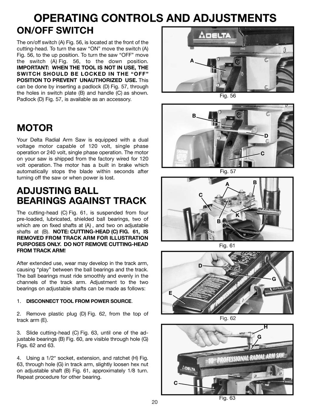
The on/off switch (A) Fig. 56, is located at the front of the
IMPORTANT: WHEN THE TOOL IS NOT IN USE, THE SWITCH SHOULD BE LOCKED IN THE “OFF” POSITION TO PREVENT UNAUTHORIZED USE. This can be done by inserting a padlock (D) Fig. 57, through the holes in switch plate (B) and handle (C) as shown. Padlock (D) Fig. 57, is available as an accessory.
MOTOR
Your Delta Radial Arm Saw is equipped with a dual voltage motor capable of 120 volt, single phase operation or 240 volt, single phase operation. The motor on your saw is shipped from the factory wired for 120 volt operation. The motor has a built in brake which automatically stops the blade within seconds after turning off the saw or when power is lost.
ADJUSTING BALL BEARINGS AGAINST TRACK
The
REMOVED FROM TRACK ARM FOR ILLUSTRATION PURPOSES ONLY. DO NOT REMOVE
After extended use, wear may develop in the track arm, causing “play” between the ball bearings and the track. The ball bearings must ride smoothly and evenly in the channels of the track arm. Adjustment to the two bearings on adjustable shafts can be made as follows:
1.DISCONNECT TOOL FROM POWER SOURCE.
2.Remove plastic plug (D) Fig. 62, from the top of track arm (E).
3.Slide
4.Using a 1/2″ socket, extension, and ratchet (H) Fig. 63, through hole (G) in track arm, slightly loosen hex nut on adjustable shaft (B) Fig. 61, approximately 1/8 turn. Repeat procedure for other bearing.
A
Fig. 56
B
![]() D
D
C
Fig. 57
A B
C
K
B
Fig. 61
D
G
E
Fig. 62
H
G
C
Fig. 63
20
