POSITIVE STOP YOKE INDEX
Yoke index lever (A) Fig. 71, activates a positive stop which positions the
POSITIVE STOP BEVEL INDEX
Bevel index knob (A) Fig. 72, provides a positive stop when positioning the saw blade at zero, 45°, and 90° left, and 90° right on the bevel scale (C). To change the angle of the saw blade, loosen bevel clamp handle (B), pull out bevel index knob (A) and tilt saw blade and motor. For zero, 45°, and 90° left, and 90° right positions, release bevel index knob (A) and saw blade will index at each of these positions. Then tighten bevel clamp handle (B). For saw blade angles between positive stops, set blade at desired angle on bevel scale (C) and tighten bevel clamp handle (B) Fig. 72.
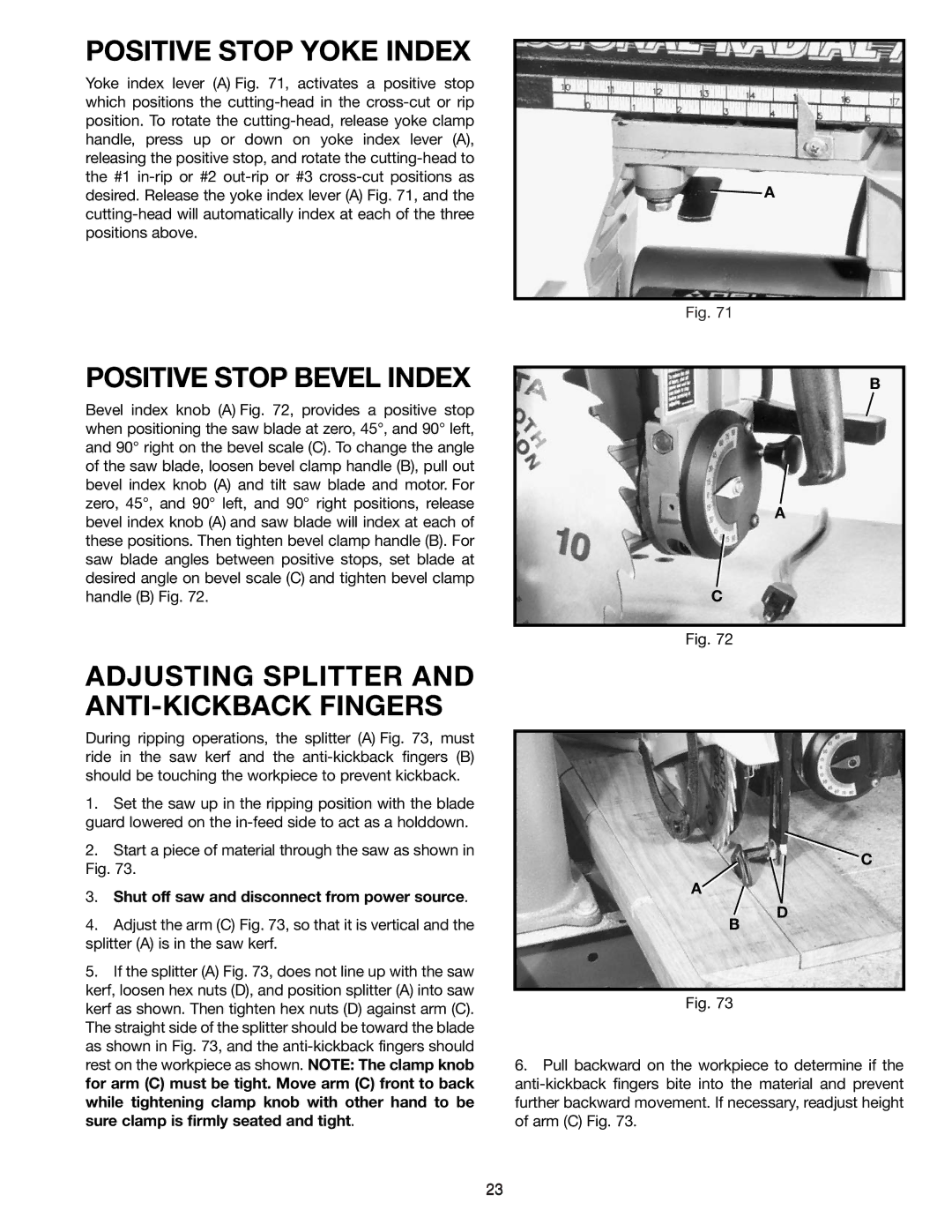
ADJUSTING SPLITTER AND ANTI-KICKBACK FINGERS
During ripping operations, the splitter (A) Fig. 73, must ride in the saw kerf and the
1.Set the saw up in the ripping position with the blade guard lowered on the
2.Start a piece of material through the saw as shown in Fig. 73.
3.Shut off saw and disconnect from power source.
4.Adjust the arm (C) Fig. 73, so that it is vertical and the splitter (A) is in the saw kerf.
5.If the splitter (A) Fig. 73, does not line up with the saw kerf, loosen hex nuts (D), and position splitter (A) into saw kerf as shown. Then tighten hex nuts (D) against arm (C). The straight side of the splitter should be toward the blade as shown in Fig. 73, and the
![]() A
A
Fig. 71
B
A
C
Fig. 72
C
A
D
B
Fig. 73
6.Pull backward on the workpiece to determine if the
23