DT3 Series Temperature Controller Instruction Sheet
Precaution
DANGER! Caution! Electric Shock!
1.Do not touch the AC terminals while the power is supplied to the controller to prevent an electric shock.
2.Make sure power is disconnected while checking the unit inside.
WARNING!
This controller is an
1.Always use recommended
2.Do not allow dust or foreign objects to fall inside the controller to prevent it from malfunctioning.
3.Never modify or disassemble the controller.
4.Do not connect anything to the “No used” terminals.
5.Make sure all wires are connected to the correct polarity of terminals.
6.Do not install and/or use the controller in places subject to:
y Dust or corrosive gases and liquid | y High humidity and high radiation |
y Vibration and shock | y High voltage and high frequency |
7.Must turn power off when wiring and changing a temperature sensor.
8.Be sure to use compensating wires that match the thermocouple types when extending or connecting the thermocouple wires.
9.Please use wires with resistance when extending or connecting a platinum resistance thermometer (RTD).
10.Please keep the wire as short as possible when wiring a platinum resistance thermometer (RTD) to the controller and please route power wires as far as possible from load wires to prevent interference and induced noise.
11.This controller is an
12.Please make sure power cables and signals from instruments are all installed properly before energizing the controller, otherwise serious damage may occur.
13.Please do not touch the terminals in the controller or try to repair the controller when power is applied to prevent an electric shock.
14.Wait at least one minute after power is disconnected to allow capacitors to discharge, and please do not touch any internal circuit within this period.
15.Do not use acid or alkaline liquids for cleaning. Please use a soft, dry cloth to clean the controller.
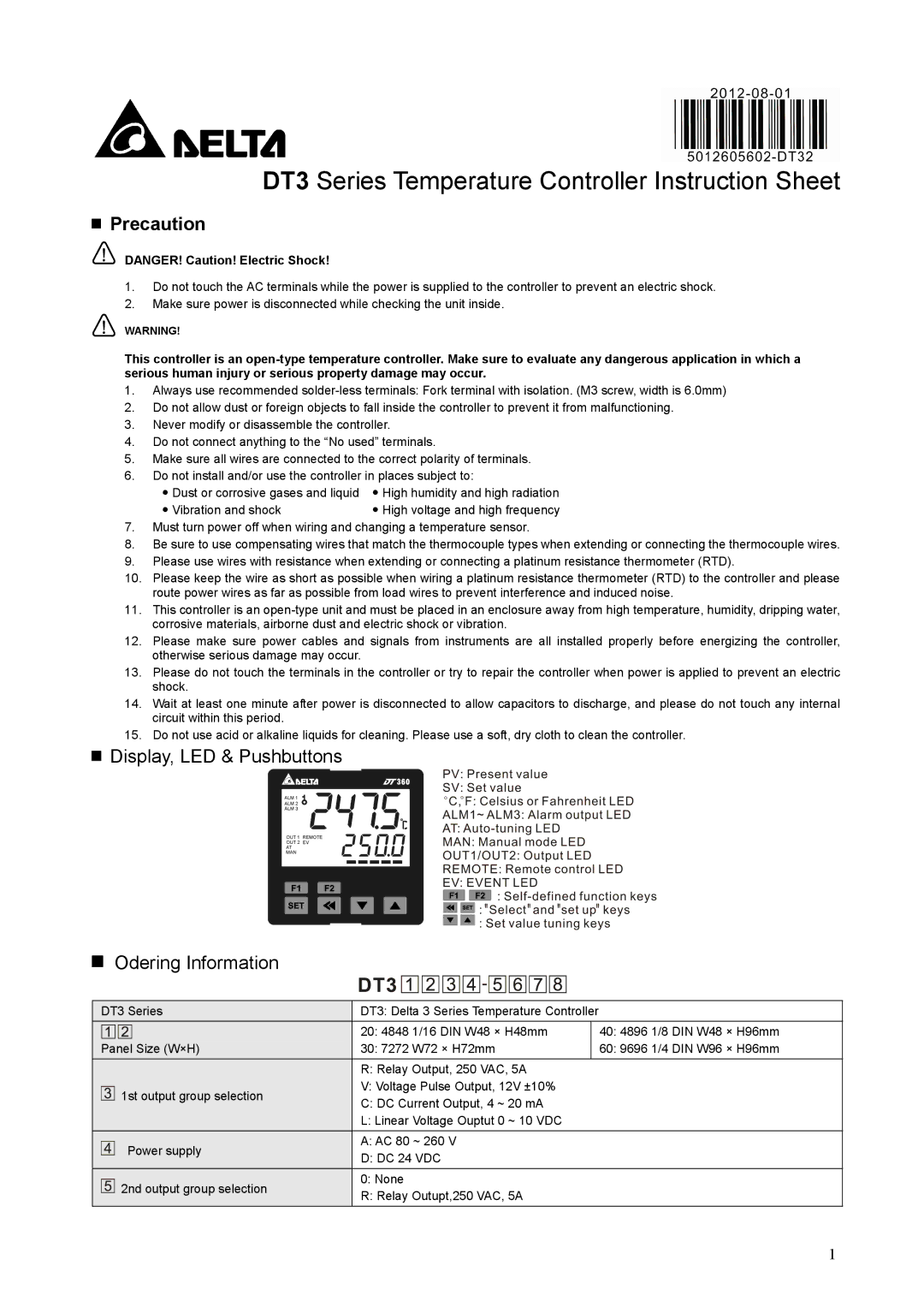
Display, LED & Pushbuttons
Odering Information
| DT3 Series | DT3: Delta 3 Series Temperature Controller |
| ||
|
|
| 20: 4848 1/16 DIN W48 × H48mm |
| 40: 4896 1/8 DIN W48 × H96mm |
| Panel Size (W×H) |
| 30: 7272 W72 × H72mm |
| 60: 9696 1/4 DIN W96 × H96mm |
|
|
| R: Relay Output, 250 VAC, 5A |
| |
| 1st output group selection |
| V: Voltage Pulse Output, 12V ±10% |
| |
|
| C: DC Current Output, 4 ~ 20 mA |
| ||
|
|
|
| ||
|
|
| L: Linear Voltage Ouptut 0 ~ 10 VDC |
| |
| Power supply |
| A: AC 80 ~ 260 V |
| |
|
| D: DC 24 VDC |
| ||
|
|
|
| ||
| 2nd output group selection |
| 0: None |
| |
|
| R: Relay Outupt,250 VAC, 5A |
| ||
|
|
|
| ||
1