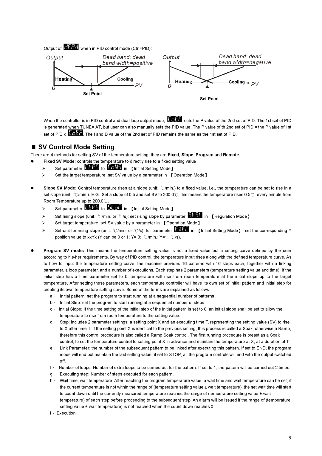
Output of ![]() when in PID control mode (Ctrl=PID):
when in PID control mode (Ctrl=PID):
Heating | Cooling | Heating | Cooling |
|
|
Set Point
Set Point
When the controller is in PID control and dual loop output mode, ![]() sets the P value of the 2nd set of PID. The 1st set of PID is generated when TUNE= AT, but user can also manually sets the PID value. The P value of th 2nd set of PID = the P value of 1st
sets the P value of the 2nd set of PID. The 1st set of PID is generated when TUNE= AT, but user can also manually sets the PID value. The P value of th 2nd set of PID = the P value of 1st
set of PID x ![]() . The I and D value of the 2nd set of PID remains the same as the 1st set of PID.
. The I and D value of the 2nd set of PID remains the same as the 1st set of PID.
SV Control Mode Setting
There are 4 methods for setting SV of the temperature setting; they are Fixed, Slope, Program and Remote.
zFixed SV Mode: controls the temperature to directly rise to a fixed setting value
¾Set parameter ![]() to
to ![]() in 【Initial Setting Mode】
in 【Initial Setting Mode】
¾Set the target temperature: set SV value by a parameter in 【Operation Mode】
zSlope SV Mode: Control temperature rises at a slope (unit: ℃/min.) to a fixed value, i.e., the temperature can be set to rise in a
set slope (unit: ℃/min.). E.G., Set a slope of 0.5 and set SV to 200.0℃; this means the temperature rises 0.5℃ every minute from Room Temperature up to 200.0℃.
¾Set parameter ![]() to
to ![]() in 【Initial Setting Mode】
in 【Initial Setting Mode】
¾Set rising slope (unit: ℃/min. or ℃/s): set rising slope by parameter ![]() in 【Regulation Mode】
in 【Regulation Mode】
¾Set target temperature: set SV value by a parameter in 【Operation Mode】
¾Set unit for rising slope (unit: ℃/min. or ℃/s): for parameter ![]() in 【Initial Setting Mode】, set the corresponding Y
in 【Initial Setting Mode】, set the corresponding Y
position value to xxYx (Y can be 0 or 1; Y= 0: ℃/min.; Y=1: ℃/s).
zProgram SV mode: This means the temperature setting value is not a fixed value but a setting curve defined by the user according to
a、 Initial pattern: set the program to start running at a sequential number of patterns
b、 Initial Step: set the program to start running at a sequential number of steps
c、 Initial Slope: If the time setting of the initial step of the initial pattern is set to 0, an initial slope shall be set to allow the temperature to rise from room temperature to the setting value.
d、 Step: includes 2 parameter settings: a setting point X and an executing time T, representing the setting value (SV) to rise to X after time T. If the setting point X is identical to the previous setting, this process is called a Soak, otherwise a Ramp, therefore this control procedure is also called a Ramp Soak control. The first running procedure is preset as a Soak control, to set the temperature control to setting point X in advance and maintain the temperature at X, at a duration of T.
e、 Link Parameter: the number of the subsequent pattern to be linked after executing this pattern. If set to END, the program mode will end but maintain the last setting value; if set to STOP, all the program controls will end with the output switched off.
f、 Number of loops: Number of extra loops to be carried out for the pattern. If set to 1, the pattern will be carried out 2 times.
g、 Executing step: Number of steps executed for each pattern.
h、 Wait time, wait temperature: After reaching the program temperature value, a wait time and wait temperature can be set; if the current temperature is not within the range of (temperature setting value ± wait temperature), the set wait time will start to count down until the currently measured temperature reaches the range of (temperature setting value ± wait temperature) of each step before proceeding to the subsequent step. An alarm will be issued if the range of (temperature setting value ± wait temperature) is not reached when the count down reaches 0.
i、 Execution:
9