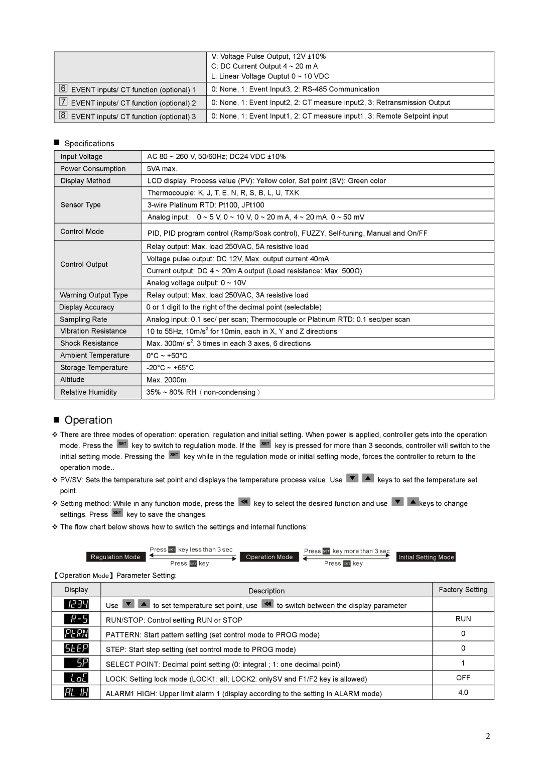
V:Voltage Pulse Output, 12V ±10%
C:DC Current Output 4 ~ 20 m A
L:Linear Voltage Ouptut 0 ~ 10 VDC
![]() EVENT inputs/ CT function (optional) 1 0: None, 1: Event Input3, 2:
EVENT inputs/ CT function (optional) 1 0: None, 1: Event Input3, 2:
![]() EVENT inputs/ CT function (optional) 2 0: None, 1: Event Input2, 2: CT measure input2, 3: Retransmission Output
EVENT inputs/ CT function (optional) 2 0: None, 1: Event Input2, 2: CT measure input2, 3: Retransmission Output
![]() EVENT inputs/ CT function (optional) 3 0: None, 1: Event Input1, 2: CT measure input1, 3: Remote Setpoint input
EVENT inputs/ CT function (optional) 3 0: None, 1: Event Input1, 2: CT measure input1, 3: Remote Setpoint input
Specifications
Input Voltage | AC 80 ~ 260 V, 50/60Hz; DC24 VDC ±10% | |
Power Consumption | 5VA max. | |
Display Method | LCD display. Process value (PV): Yellow color, Set point (SV): Green color | |
| Thermocouple: K, J, T, E, N, R, S, B, L, U, TXK | |
Sensor Type | ||
|
| |
| Analog input: 0 ~ 5 V, 0 ~ 10 V, 0 ~ 20 m A, 4 ~ 20 mA, 0 ~ 50 mV | |
Control Mode | PID, PID program control (Ramp/Soak control), FUZZY, | |
| ||
| Relay output: Max. load 250VAC, 5A resistive load | |
|
| |
Control Output | Voltage pulse output: DC 12V, Max. output current 40mA | |
| ||
Current output: DC 4 ~ 20m A output (Load resistance: Max. 500Ω) | ||
| ||
| Analog voltage output: 0 ~ 10V | |
Warning Output Type | Relay output: Max. load 250VAC, 3A resistive load | |
Display Accuracy | 0 or 1 digit to the right of the decimal point (selectable) | |
Sampling Rate | Analog input: 0.1 sec/ per scan; Thermocouple or Platinum RTD: 0.1 sec/per scan | |
Vibration Resistance | 10 to 55Hz, 10m/s2 for 10min, each in X, Y and Z directions | |
Shock Resistance | Max. 300m/ s2, 3 times in each 3 axes, 6 directions | |
Ambient Temperature | 0°C ~ +50°C | |
Storage Temperature | ||
Altitude | Max. 2000m | |
Relative Humidity | 35% ~ 80% | |
|
|
Operation
There are three modes of operation: operation, regulation and initial setting. When power is applied, controller gets into the operation
mode. Press the ![]() key to switch to regulation mode. If the
key to switch to regulation mode. If the ![]() key is pressed for more than 3 seconds, controller will switch to the
key is pressed for more than 3 seconds, controller will switch to the
initial setting mode. Pressing the ![]() key while in the regulation mode or initial setting mode, forces the controller to return to the operation mode..
key while in the regulation mode or initial setting mode, forces the controller to return to the operation mode..
PV/SV: Sets the temperature set point and displays the temperature process value. Use ![]()
![]() keys to set the temperature set point.
keys to set the temperature set point.
Setting method: While in any function mode, press the ![]() key to select the desired function and use
key to select the desired function and use ![]()
![]() keys to change
keys to change
settings. Press ![]() key to save the changes.
key to save the changes.
The flow chart below shows how to switch the settings and internal functions:
Regulation Mode
Press ![]() key less than 3 sec
key less than 3 sec
Press ![]() key
key
Operation Mode
Press ![]() key more than 3 sec
key more than 3 sec
Press ![]() key
key
Initial Setting Mode
【Operation Mode】Parameter Setting:
Display |
| Description | Factory Setting | |
| Use | to set temperature set point, use | to switch between the display parameter |
|
| RUN/STOP: Control setting RUN or STOP |
| RUN | |
|
|
| ||
| PATTERN: Start pattern setting (set control mode to PROG mode) | 0 | ||
| STEP: Start step setting (set control mode to PROG mode) | 0 | ||
|
|
| ||
| SELECT POINT: Decimal point setting (0: integral ; 1: one decimal point) | 1 | ||
| LOCK: Setting lock mode (LOCK1: all; LOCK2: onlySV and F1/F2 key is allowed) | OFF | ||
|
|
| ||
| ALARM1 HIGH: Upper limit alarm 1 (display according to the setting in ALARM mode) | 4.0 | ||
2
