| ALARM mode) |
|
|
|
| |
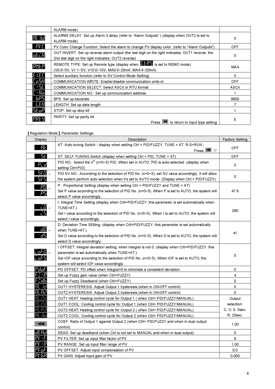
| ALARM3 DELAY: Set up Alarm 3 delay (refer to “Alarm Outputs” ) (display when OUT2 is set to |
| 0 | |||
| ALARM mode) |
|
|
| ||
|
|
|
|
| ||
| PV Color Change Function: Select the alarm to change PV display color. (refer to "Alarm Outputs") | OFF | ||||
| OUT INVERT: Set up reverse alarm output (the last digit on the right indicates: OUT1 reverse; the |
| 0 | |||
| 2nd last digit on the right indicates: OUT2 reverse) |
|
|
| ||
|
|
|
|
| ||
| REMOTE TYPE: Set up Remote type (display when | is set to REMO mode) |
| MA4 | ||
| (V0:0~5V; V1:1~5V; V10:0~10V; MA0:0~20mA; MA4:4~20mA) |
|
| |||
|
|
|
| |||
| Select auxiliary function (refer to SV Control Mode Setting) |
|
|
| 0 | |
| COMMUNICATION WRITE: Enable/disable communication |
|
| OFF | ||
| COMMUNICATION SELECT: Select ASCII or RTU format |
|
|
| ASCII | |
| COMMUNICATION NO.: Set up communication address |
|
|
| 1 | |
| BPS: Set up baudrate |
|
|
| 9600 | |
| LENGTH: Set up data length |
|
|
| 7 | |
| STOP: Set up stop bit |
|
|
| 1 | |
| PARITY: Set up parity bit |
|
|
| E | |
|
|
| Press | to return to input type setting | ||
|
|
|
| |||
【Regulation Mode】Parameter Settings: |
|
|
|
| ||
Display |
| Description |
|
|
| Factory Setting |
|
| AT: |
| OFF | ||
|
|
|
| Press | V | |
|
|
|
|
| ||
|
| ST: |
| OFF | ||
|
| PID NO.: Select the nth (n=0~5) PID. When set in AUTO, PID is |
| 0 | ||
|
| setting Ctrl=PID) |
|
|
| |
|
|
|
|
|
| |
~ |
| PID SV NO.: Accordinig to the selection of PID No. (n=0~5), set SV value accordingly. It will allow | 0 | |||
|
| the system perform auto selection when it’s set to AUTO mode. (Display when Ctrl = PID/FUZZY). | ||||
|
|
| ||||
~ |
| P : Proportional Setting (display when setting Ctrl = PID/FUZZY and TUNE = AT) |
|
| ||
| Set P value according to the selection of PID No. (n=0~5). When P is set to AUTO, the system will | 47.6 | ||||
|
| |||||
|
| select P value accordingly. |
|
|
|
|
|
| I: Integral Time Setting (display when Crtl=PID/FUZZY; this parameter is set automatically when |
| |||
~ |
| TUNE=AT.) |
|
|
| 260 |
|
| Set I value according to the selection of PID No. (n=0~5). When I is set to AUTO, the system will | ||||
|
|
| ||||
|
| select I value accordingly. |
|
|
|
|
|
| D: Deviation Time SEtting: (display when Crtl=PID/FUZZY; this parameter is set automatically |
|
| ||
~ |
| when TUNE=AT.) |
|
|
| 41 |
|
| Set D value according to the selection of PID No. (n=0~5). When D is set to AUTO, the system will | ||||
|
|
| ||||
|
| select D value accordingly. |
|
|
|
|
|
| I OFFSET: Integral deviation setting, when Integral is not 0. (display when Crtl=PID/FUZZY; this |
| |||
~ |
| parameter is set automatically when TUNE=AT.) |
|
|
| 0 |
|
| Set IOF value according to the selection of PID No. (n=0~5). When IOF is set to AUTO, the |
| |||
|
|
|
| |||
|
| system will select IOF value accordingly. |
|
|
|
|
|
| PD OFFSET: PD offset when Integral=0 to eliminate a consistent deviation. |
| 0 | ||
|
| Set up Fuzzy gain value (when Ctrl=FUZZY) |
|
|
| 4 |
|
| Set up Fuzzy Deadband (when Ctrl=FUZZY) |
|
|
| 0 |
|
| OUT1 HYSTERESIS: Adjust Output 1 hysteresis (when in ON/OFF control) |
| 0 | ||
|
| OUT2 HYSTERESIS: Adjust Output 2 hysteresis (when in ON/OFF control) |
| 0 | ||
|
| OUT1 HEAT: Heating control cycle for Output 1 ( when Ctrl= PID/FUZZY/MANUAL) |
| Output | ||
|
| OUT1 COOL: Cooling control cycle for Output 1 (when Ctrl= PID/FUZZY/MANUAL) |
| selection: | ||
|
| OUT2 HEAT: Heating control cycle for Output 2 ( when Ctrl= PID/FUZZY/MANUAL) |
| C; V; S: 5sec. | ||
|
| OUT2 COOL: Cooling control cycle for Output 2 (when Ctrl= PID/FUZZY/MANUAL) |
| R: 20sec. | ||
|
| COEF: Ratio of Output 1 against Output 2 (when Ctrl= PID/FUZZY and when in dual output |
| 1.00 | ||
|
| control) |
|
|
| |
|
|
|
|
|
| |
|
| DEAD: Set up deadband (when Ctrl is not set to MANUAL and when in dual output) |
| 0 | ||
|
| PV FILTER: Set up input filter factor of PV |
|
|
| 8 |
|
| PV RANGE: Set up input filter range of PV |
|
|
| 1.00 |
|
| PV OFFSET: Adjust input compensation of PV |
|
|
| 0.0 |
|
| PV GAIN: Adjust input gain of PV |
|
|
| 0.000 |
4
