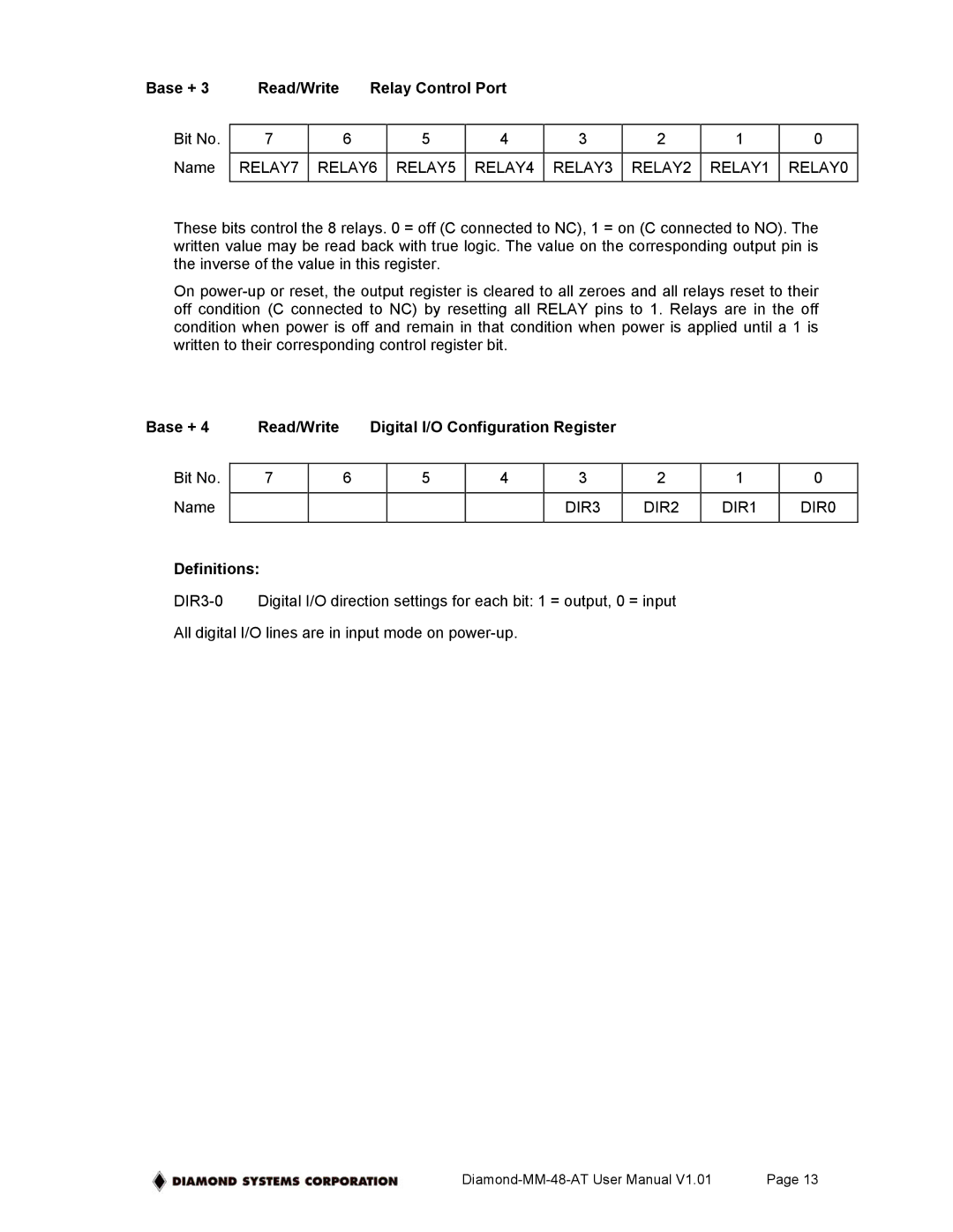
Base + 3 | Read/Write | Relay Control Port |
|
|
|
| |||
|
|
|
|
|
|
|
|
|
|
Bit No. | 7 |
| 6 | 5 | 4 | 3 | 2 | 1 | 0 |
|
|
|
|
|
|
|
|
| |
Name | RELAY7 | RELAY6 | RELAY5 | RELAY4 | RELAY3 | RELAY2 | RELAY1 | RELAY0 | |
|
|
|
|
|
|
|
|
|
|
These bits control the 8 relays. 0 = off (C connected to NC), 1 = on (C connected to NO). The written value may be read back with true logic. The value on the corresponding output pin is the inverse of the value in this register.
On
Base + 4 | Read/Write |
| Digital I/O Configuration Register |
|
|
| ||||
|
|
|
|
|
|
|
|
|
|
|
Bit No. | 7 |
| 6 |
| 5 | 4 | 3 | 2 | 1 | 0 |
|
|
|
|
|
|
|
|
|
|
|
Name |
|
|
|
|
|
| DIR3 | DIR2 | DIR1 | DIR0 |
|
|
|
|
|
|
|
|
|
|
|
Definitions:
All digital I/O lines are in input mode on
Page 13 |