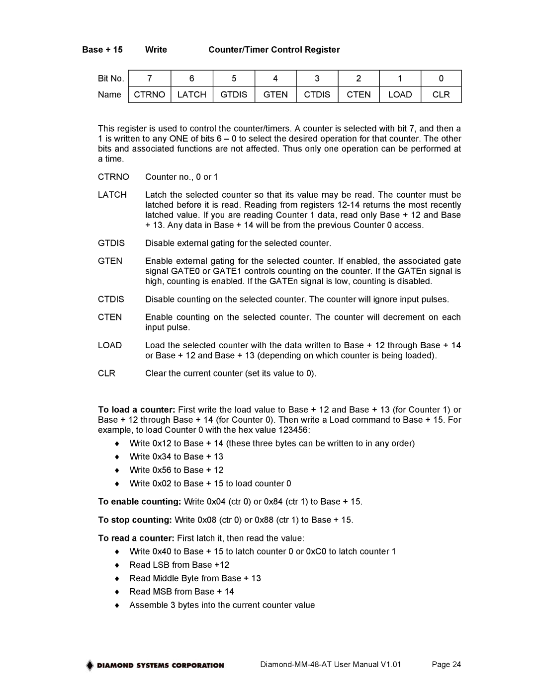
Base + 15 | Write |
| Counter/Timer Control Register |
|
|
| ||||
|
|
|
|
|
|
|
|
|
|
|
Bit No. | 7 | 6 |
| 5 | 4 | 3 |
| 2 | 1 | 0 |
|
|
|
|
|
|
|
|
|
|
|
Name | CTRNO | LATCH |
| GTDIS | GTEN | CTDIS |
| CTEN | LOAD | CLR |
|
|
|
|
|
|
|
|
|
|
|
This register is used to control the counter/timers. A counter is selected with bit 7, and then a 1 is written to any ONE of bits 6 – 0 to select the desired operation for that counter. The other bits and associated functions are not affected. Thus only one operation can be performed at a time.
CTRNO | Counter no., 0 or 1 |
LATCH | Latch the selected counter so that its value may be read. The counter must be |
| latched before it is read. Reading from registers |
| latched value. If you are reading Counter 1 data, read only Base + 12 and Base |
| + 13. Any data in Base + 14 will be from the previous Counter 0 access. |
GTDIS | Disable external gating for the selected counter. |
GTEN | Enable external gating for the selected counter. If enabled, the associated gate |
| signal GATE0 or GATE1 controls counting on the counter. If the GATEn signal is |
| high, counting is enabled. If the GATEn signal is low, counting is disabled. |
CTDIS | Disable counting on the selected counter. The counter will ignore input pulses. |
CTEN | Enable counting on the selected counter. The counter will decrement on each |
| input pulse. |
LOAD | Load the selected counter with the data written to Base + 12 through Base + 14 |
| or Base + 12 and Base + 13 (depending on which counter is being loaded). |
CLR | Clear the current counter (set its value to 0). |
To load a counter: First write the load value to Base + 12 and Base + 13 (for Counter 1) or Base + 12 through Base + 14 (for Counter 0). Then write a Load command to Base + 15. For example, to load Counter 0 with the hex value 123456:
♦Write 0x12 to Base + 14 (these three bytes can be written to in any order)
♦Write 0x34 to Base + 13
♦Write 0x56 to Base + 12
♦Write 0x02 to Base + 15 to load counter 0
To enable counting: Write 0x04 (ctr 0) or 0x84 (ctr 1) to Base + 15.
To stop counting: Write 0x08 (ctr 0) or 0x88 (ctr 1) to Base + 15.
To read a counter: First latch it, then read the value:
♦Write 0x40 to Base + 15 to latch counter 0 or 0xC0 to latch counter 1
♦Read LSB from Base +12
♦Read Middle Byte from Base + 13
♦Read MSB from Base + 14
♦Assemble 3 bytes into the current counter value
Page 24 |