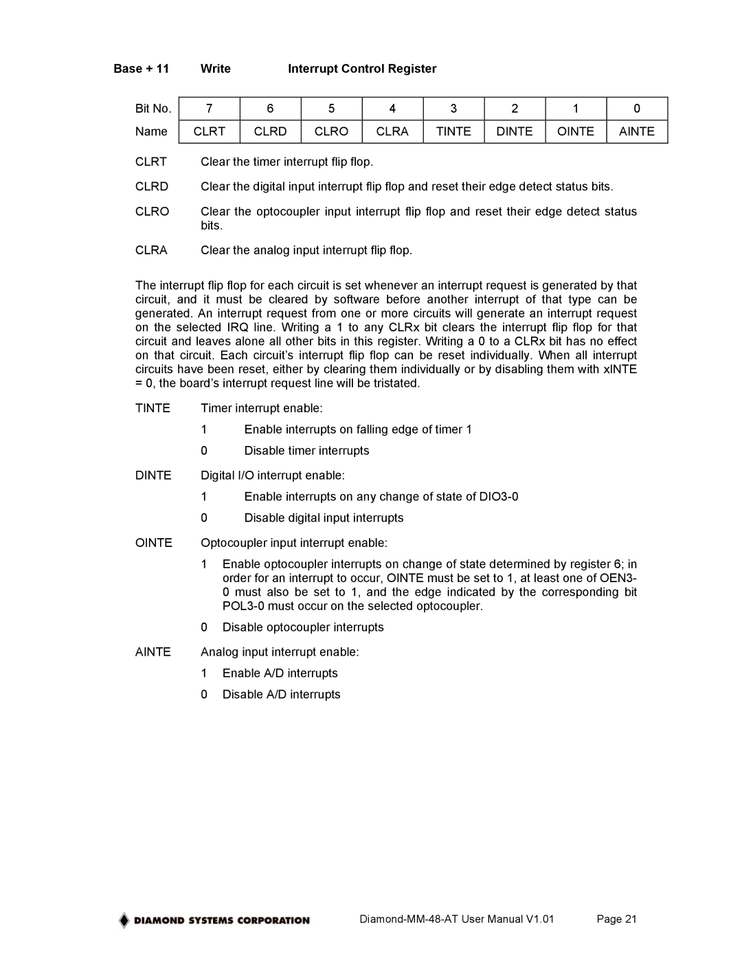
Base + 11 | Write |
| Interrupt Control Register |
|
|
|
| ||||
|
|
|
|
|
|
|
|
|
|
|
|
Bit No. | 7 | 6 |
| 5 |
| 4 | 3 | 2 | 1 |
| 0 |
|
|
|
|
|
|
|
|
|
|
|
|
Name | CLRT | CLRD |
| CLRO |
| CLRA | TINTE | DINTE | OINTE |
| AINTE |
|
|
|
|
|
|
|
|
|
|
| |
CLRT | Clear the timer interrupt flip flop. |
|
|
|
|
|
| ||||
CLRD | Clear the digital input interrupt flip flop and reset their edge detect status bits. |
| |||||||||
CLRO | Clear the optocoupler input interrupt flip flop and reset their edge detect status | ||||||||||
| bits. |
|
|
|
|
|
|
|
|
|
|
CLRA | Clear the analog input interrupt flip flop. |
|
|
|
|
| |||||
The interrupt flip flop for each circuit is set whenever an interrupt request is generated by that circuit, and it must be cleared by software before another interrupt of that type can be generated. An interrupt request from one or more circuits will generate an interrupt request on the selected IRQ line. Writing a 1 to any CLRx bit clears the interrupt flip flop for that circuit and leaves alone all other bits in this register. Writing a 0 to a CLRx bit has no effect on that circuit. Each circuit’s interrupt flip flop can be reset individually. When all interrupt circuits have been reset, either by clearing them individually or by disabling them with xINTE = 0, the board’s interrupt request line will be tristated.
TINTE | Timer interrupt enable: | |
| 1 | Enable interrupts on falling edge of timer 1 |
| 0 | Disable timer interrupts |
DINTE | Digital I/O interrupt enable: | |
| 1 | Enable interrupts on any change of state of |
| 0 | Disable digital input interrupts |
OINTE | Optocoupler input interrupt enable: | |
| 1 | Enable optocoupler interrupts on change of state determined by register 6; in |
|
| order for an interrupt to occur, OINTE must be set to 1, at least one of OEN3- |
|
| 0 must also be set to 1, and the edge indicated by the corresponding bit |
|
| |
| 0 | Disable optocoupler interrupts |
AINTE | Analog input interrupt enable: | |
| 1 | Enable A/D interrupts |
| 0 | Disable A/D interrupts |
Page 21 |