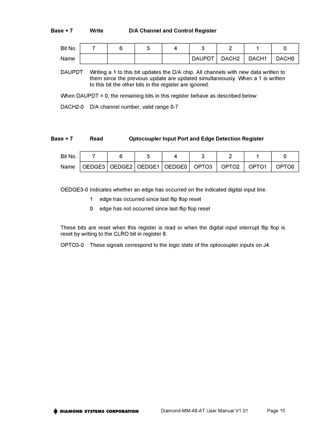
Base + 7 | Write |
| D/A Channel and Control Register |
|
|
| ||||
|
|
|
|
|
|
|
|
|
| |
Bit No. |
| 7 | 6 |
| 5 | 4 | 3 | 2 | 1 | 0 |
|
|
|
|
|
|
|
|
|
|
|
Name |
|
|
|
|
|
| DAUPDT | DACH2 | DACH1 | DACH0 |
|
|
|
|
|
|
|
|
|
| |
DAUPDT | Writing a 1 to this bit updates the D/A chip. All channels with new data written to | |||||||||
|
| them since the previous update are updated simultaneously. When a 1 is written | ||||||||
|
| to this bit the other bits in the register are ignored. |
|
|
| |||||
When DAUPDT = 0, the remaining bits in this register behave as described below:
Base + 7 | Read | Optocoupler Input Port and Edge Detection Register |
| |||||
|
|
|
|
|
|
|
|
|
Bit No. | 7 | 6 | 5 | 4 | 3 | 2 | 1 | 0 |
|
|
|
|
|
|
|
|
|
Name | OEDGE3 | OEDGE2 | OEDGE1 | OEDGE0 | OPTO3 | OPTO2 | OPTO1 | OPTO0 |
|
|
|
|
|
|
|
|
|
0 edge has not occurred since last flip flop reset
These bits are reset when this register is read or when the digital input interrupt flip flop is reset by writing to the CLRO bit in register 8.
Page 15 |