3. I/O HEADER PINOUT AND PIN DESCRIPTION
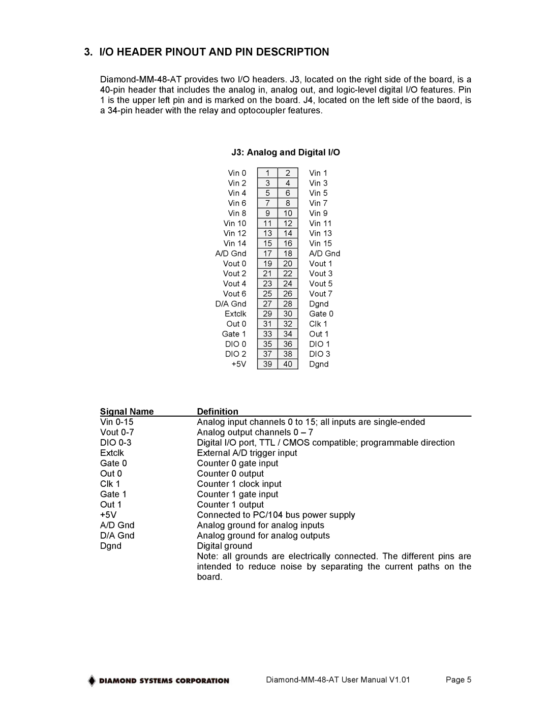
J3: Analog and Digital I/O
Vin 0 | 1 | 2 | Vin 1 |
Vin 2 | 3 | 4 | Vin 3 |
Vin 4 | 5 | 6 | Vin 5 |
Vin 6 | 7 | 8 | Vin 7 |
Vin 8 | 9 | 10 | Vin 9 |
Vin 10 | 11 | 12 | Vin 11 |
Vin 12 | 13 | 14 | Vin 13 |
Vin 14 | 15 | 16 | Vin 15 |
A/D Gnd | 17 | 18 | A/D Gnd |
Vout 0 | 19 | 20 | Vout 1 |
Vout 2 | 21 | 22 | Vout 3 |
Vout 4 | 23 | 24 | Vout 5 |
Vout 6 | 25 | 26 | Vout 7 |
D/A Gnd | 27 | 28 | Dgnd |
Extclk | 29 | 30 | Gate 0 |
Out 0 | 31 | 32 | Clk 1 |
Gate 1 | 33 | 34 | Out 1 |
DIO 0 | 35 | 36 | DIO 1 |
DIO 2 | 37 | 38 | DIO 3 |
+5V | 39 | 40 | Dgnd |
Signal Name | Definition |
Vin | Analog input channels 0 to 15; all inputs are |
Vout | Analog output channels 0 – 7 |
DIO | Digital I/O port, TTL / CMOS compatible; programmable direction |
Extclk | External A/D trigger input |
Gate 0 | Counter 0 gate input |
Out 0 | Counter 0 output |
Clk 1 | Counter 1 clock input |
Gate 1 | Counter 1 gate input |
Out 1 | Counter 1 output |
+5V | Connected to PC/104 bus power supply |
A/D Gnd | Analog ground for analog inputs |
D/A Gnd | Analog ground for analog outputs |
Dgnd | Digital ground |
| Note: all grounds are electrically connected. The different pins are |
| intended to reduce noise by separating the current paths on the |
| board. |
Page 5 |