The PULSE CT variable for each channel can be set to any value between 1 and 65,535. In setting the PULSE CT, the x10 button will increase this number by a factor of ten and the encoder wheel will increase/decrease the number of pulses incrementally by one. For example, to set the count to 1,500, first set the count to 15 using the encoder wheel, then press the X10 button two times. The first press will increment the count to 150, and the second to 1,500.
Pressing the OUTPUT button enables the output pulse series. The Pulse On LED will illuminate until the pulse series is completed, at which time the LED will extinguish. Each time the PULSE ON button is pressed, the output pulse series will be generated.
In Internal PRF mode, the frequency (repetition rate) of the pulses are determined by the internal frequency generator. If externally triggered, the frequency of the pulses is determined by the frequency of the input trigger.
The delay of each of the outputs is relative to the leading edge of the T0 SYNC output.
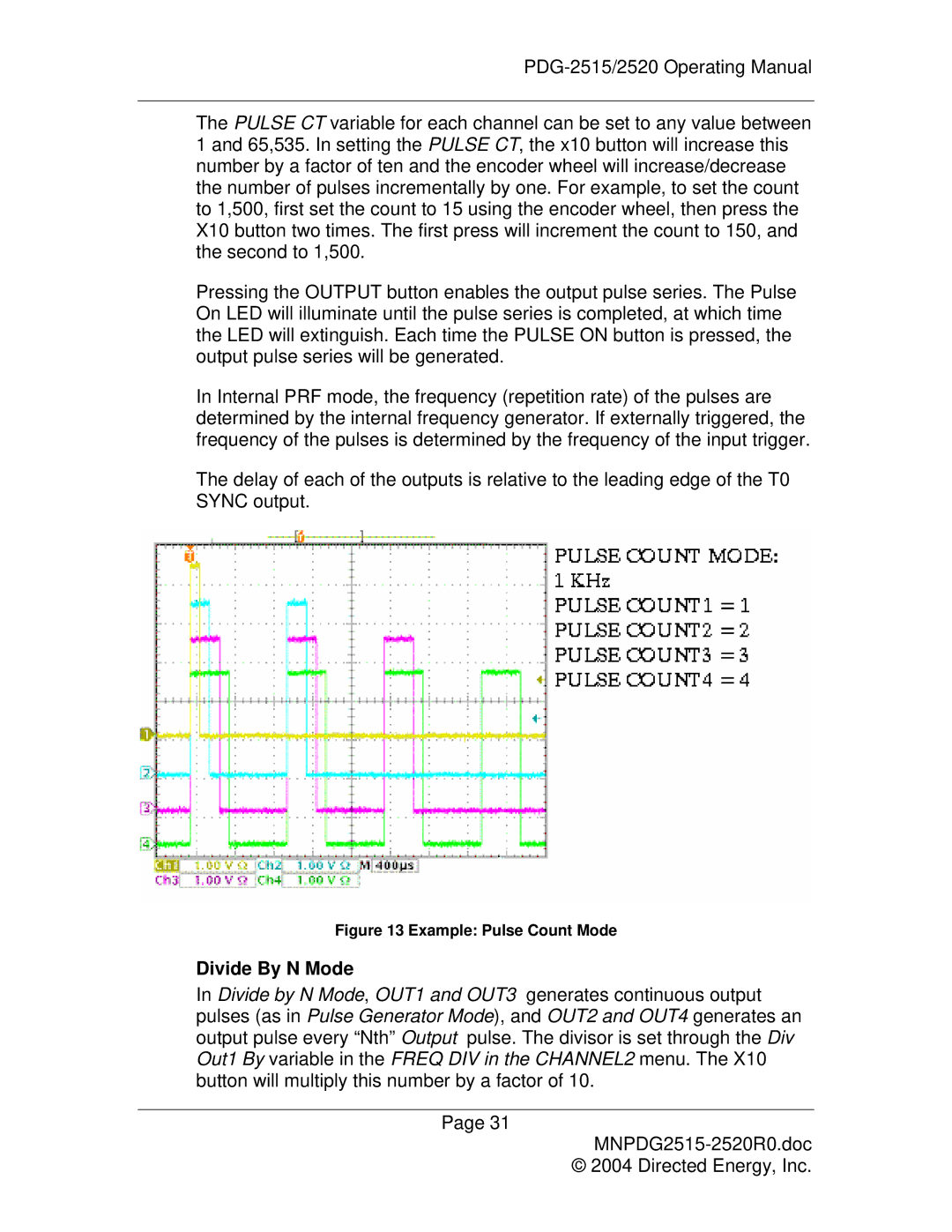
Figure 13 Example: Pulse Count Mode
Divide By N Mode
In Divide by N Mode, OUT1 and OUT3 generates continuous output pulses (as in Pulse Generator Mode), and OUT2 and OUT4 generates an output pulse every “Nth” Output pulse. The divisor is set through the Div Out1 By variable in the FREQ DIV in the CHANNEL2 menu. The X10 button will multiply this number by a factor of 10.
Page 31
© 2004 Directed Energy, Inc.