Reply:
The reply generated will be either response to the data sent to the unit, as in a query, or an error code. The error code will be prefaced by a ‘#’ and then the ascii code itself. The codes are explained below. The error code, whether it is 0 (which indicates NO ERROR) or a valid error is prefaced by the ‘#’ character to distinguish the data from a valid reply. For example, if the pulse width was queried (CHNx:PULS:WIDT?), a valid response would not have a ‘#’ character as the first character, but if there was an error (such as invalid channel, parse error, etc.) the response would send a ‘#’ character as it’s first byte.
The ASCII commands:
The commands sent are in four letter words separated by a colon. The data is separated by a single white space character (0x20) and is in the from x.xxE+xx. For example, to set the frequency to 1.35 KHz you would send the string CHAN:PULS:FREQ 1.35E+03. Each channel in the unit is distinguished by a CHNx, where x is the channel the remote is talking to. For example, to set the pulse width of channel 2 to 150 us, the string sent would be CHN2:PULS:WIDT
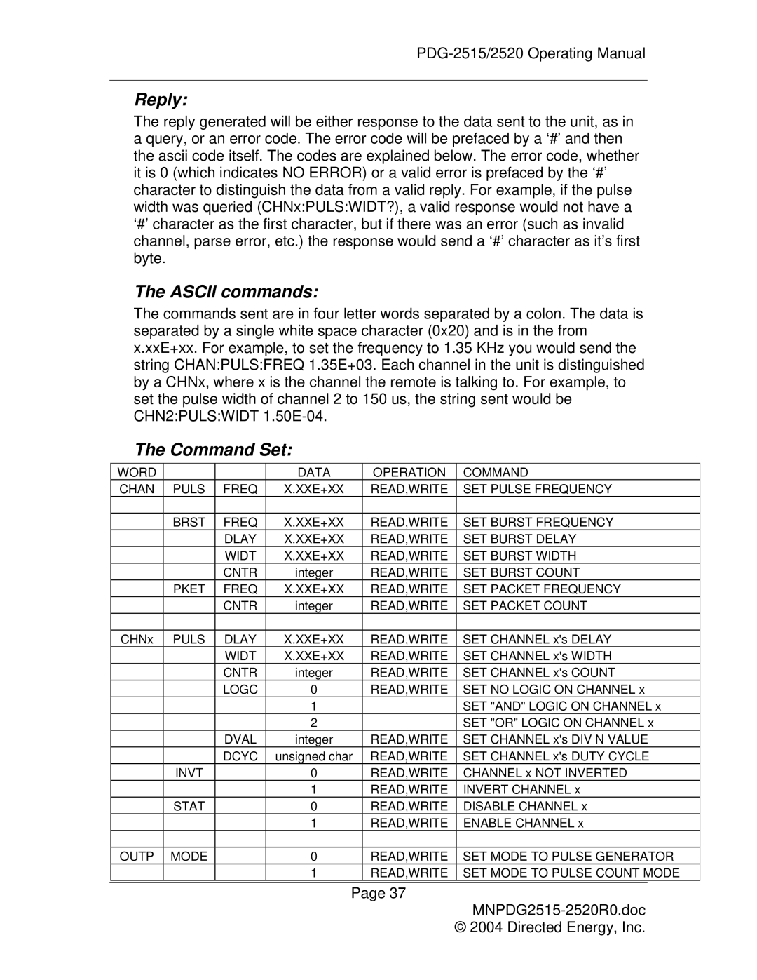
The Command Set:
WORD |
|
| DATA | OPERATION | COMMAND | |
CHAN | PULS | FREQ | X.XXE+XX | READ,WRITE | SET PULSE FREQUENCY | |
|
|
|
|
| SET BURST FREQUENCY | |
| BRST | FREQ | X.XXE+XX | READ,WRITE | ||
|
| DLAY | X.XXE+XX | READ,WRITE | SET BURST DELAY | |
|
| WIDT | X.XXE+XX | READ,WRITE | SET BURST WIDTH | |
|
| CNTR | integer | READ,WRITE | SET BURST COUNT | |
| PKET | FREQ | X.XXE+XX | READ,WRITE | SET PACKET FREQUENCY | |
|
| CNTR | integer | READ,WRITE | SET PACKET COUNT | |
|
|
|
|
| SET CHANNEL x's DELAY | |
CHNx | PULS | DLAY | X.XXE+XX | READ,WRITE | ||
|
| WIDT | X.XXE+XX | READ,WRITE | SET CHANNEL x's WIDTH | |
|
| CNTR | integer | READ,WRITE | SET CHANNEL x's COUNT | |
|
| LOGC | 0 | READ,WRITE | SET NO LOGIC ON CHANNEL x | |
|
|
| 1 |
| SET "AND" LOGIC ON CHANNEL x | |
|
|
| 2 |
| SET "OR" LOGIC ON CHANNEL x | |
|
| DVAL | integer | READ,WRITE | SET CHANNEL x's DIV N VALUE | |
|
| DCYC | unsigned char | READ,WRITE | SET CHANNEL x's DUTY CYCLE | |
| INVT |
| 0 | READ,WRITE | CHANNEL x NOT INVERTED | |
|
|
| 1 | READ,WRITE | INVERT CHANNEL x | |
| STAT |
| 0 | READ,WRITE | DISABLE CHANNEL x | |
|
|
| 1 | READ,WRITE | ENABLE CHANNEL x | |
|
|
|
|
| SET MODE TO PULSE GENERATOR | |
OUTP | MODE |
| 0 | READ,WRITE | ||
|
|
| 1 | READ,WRITE | SET MODE TO PULSE COUNT MODE | |
|
|
|
|
|
|
|
Page 37
MNPDG2515-2520R0.doc
© 2004 Directed Energy, Inc.