| ||
|
|
|
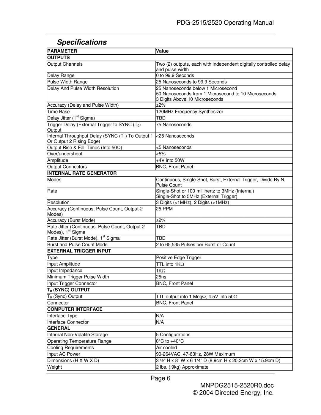
Specifications |
|
|
PARAMETER | Value | |
OUTPUTS |
|
|
Output Channels | Two (2) outputs, each with independent digitally controlled delay | |
| and pulse width | |
Delay Range | 0 to 99.9 Seconds | |
Pulse Width Range | 25 Nanoseconds to 99.9 Seconds | |
Delay And Pulse Width Resolution | 25 Nanoseconds below 1 Microsecond | |
| 50 Nanoseconds from 1 Microsecond to 10 Microseconds | |
| 3 Digits Above 10 Microseconds | |
Accuracy (Delay and Pulse Width) | ±2% |
|
Time Base | 120MHz Frequency Synthesizer | |
Delay Jitter (1st Sigma) | TBD | |
Trigger Delay (External Trigger to SYNC (T0) | 75 Nanoseconds | |
Output |
|
|
Internal Throughput Delay (SYNC (T0) To Output 1 | <25 Nanoseconds | |
Or Output 2 Rising Edge) |
|
|
Output Rise & Fall Times (Into 50Ω) | <5 Nanoseconds | |
Over/undershoot | <5% |
|
Amplitude | +4V into 50W | |
Output Connectors | BNC, Front Panel | |
INTERNAL RATE GENERATOR |
|
|
Modes | Continuous, | |
| Pulse Count | |
Rate | ||
| ||
Resolution | 3 Digits (<1MHz), 2 Digits (>1MHz) | |
Accuracy (Continuous, Pulse Count, | 25 PPM | |
Modes) |
|
|
Accuracy (Burst Mode) | ±2% |
|
Rate Jitter (Continuous, Pulse Count, | TBD | |
Modes), 1st Sigma |
|
|
Rate Jitter (Burst Mode), 1st Sigma | TBD | |
Burst and Pulse Count Mode | 2 to 65,535 Pulses per Burst or Count | |
EXTERNAL TRIGGER INPUT |
|
|
Type | Positive Edge Trigger | |
Input Amplitude | TTL into 1KΩ | |
Input Impedance | 1KΩ | |
Minimum Trigger Pulse Width | 25ns | |
Input Trigger Connector | BNC, Front Panel | |
T0 (SYNC) OUTPUT |
|
|
T0 (Sync) Output | TTL output into 1 MegΩ, 4.5V into 50Ω | |
Connector | BNC, Front Panel | |
COMPUTER INTERFACE |
|
|
Interface Type | N/A | |
Interface Connector | N/A | |
GENERAL |
|
|
Internal | 5 Configurations | |
Operating Temperature Range | 0°C to +40°C | |
Cooling Requirements | Air cooled | |
Input AC Power | ||
Dimensions (H X W X D) | 3 ½” H x 8” W x 6 1/4” D (8.9cm H x 20.3cm W x 15.9cm D) | |
Weight | 2 lbs. (.9kg) Approximate | |
Page 6
© 2004 Directed Energy, Inc.