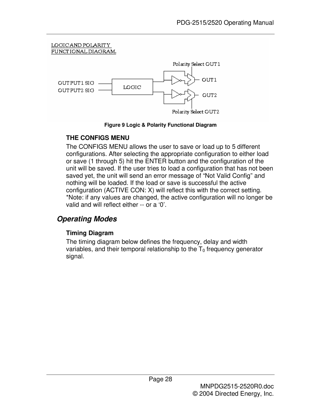
Figure 9 Logic & Polarity Functional Diagram
THE CONFIGS MENU
The CONFIGS MENU allows the user to save or load up to 5 different configurations. After selecting the appropriate configuration to either load or save (1 through 5) hit the ENTER button and the configuration of the unit will be saved. If the user tries to load a configuration that has not been saved yet, the unit will send an error message of “Not Valid Config” and nothing will be loaded. If the load or save is successful the active configuration (ACTIVE CON: X) will reflect this with the correct setting. *Note: if any values are changed, the active configuration will no longer be valid and will reflect either
Operating Modes
Timing Diagram
The timing diagram below defines the frequency, delay and width variables, and their temporal relationship to the T0 frequency generator signal.
Page 28
© 2004 Directed Energy, Inc.